|
Big Clock
|

|
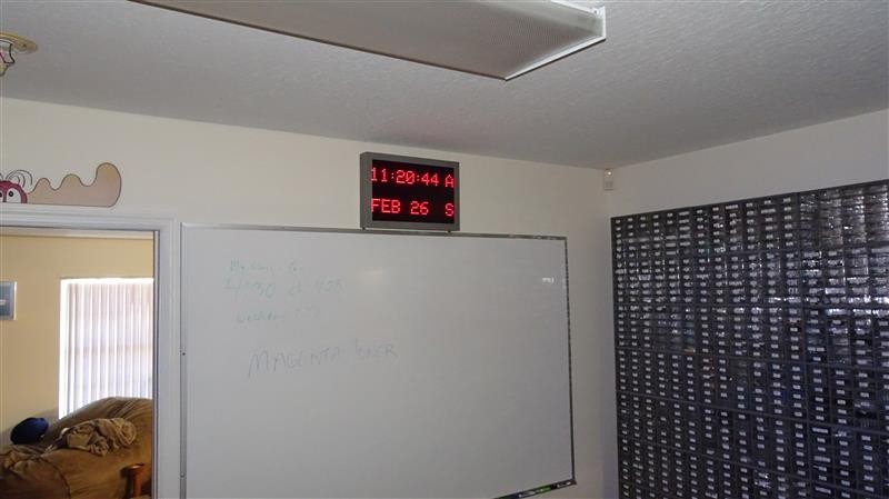
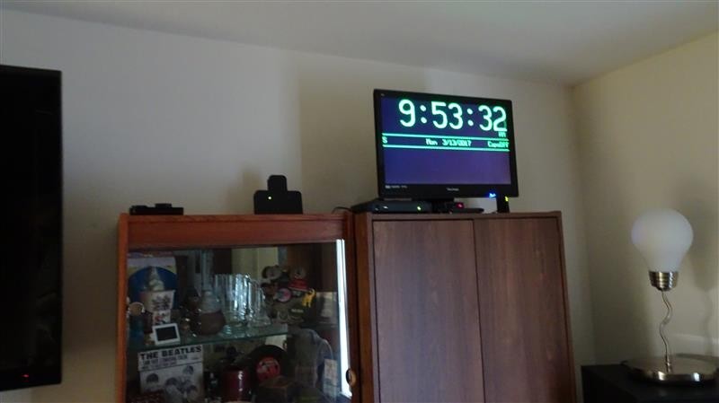
It’s hard to find a nice big clock. So, I took a product I had designed for one of my many failed entrepreneurial attempts and made the Big Clock. The “front desk” element of my “eCheckIn” system outputs a simple VGA signal to drive a modern PC monitor. Since I had an LED backlit 23” monitor sitting around, I thought I would make a clock with huge green digits. It would sit on top of the cabinets in our living room so we could see it throughout the living and dining room areas. So this was entirely a software project, having designed and built the unit several years ago.
While I was at it, since I had that big screen, I decided to also show the day and date. In the lower part of the screen, I have a 6 line by 40 character text area. Here, using a wireless keyboard, you can scroll through to any day of the year and enter/edit reminders for that day in non-volatile memory. Things like a reminder to get ready for a car show, or just some program to watch on that day. When that day arrives, the text you entered will be displayed.
|
|
Electronics & Maker Projects (page 2) |

|
The photo above shows the unit in Edit mode. When you are looking at any day other than the current one, either scrolling through or editing, the date and text areas turn amber. Here we are on a future day entering reminder text.
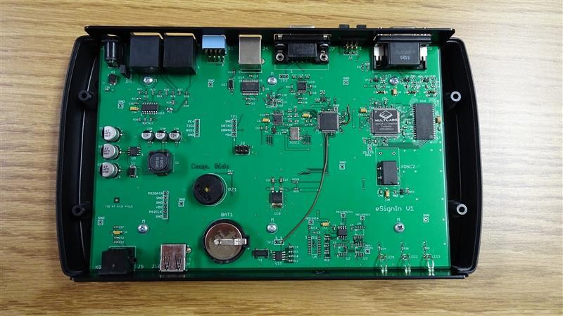
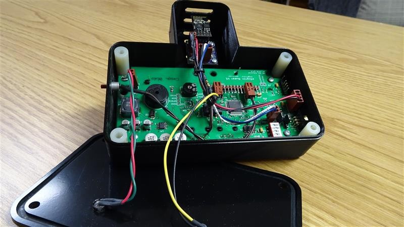
To the left is a photo of the electronics. You can see the backup battery for the Real Time Clock (RTC). It keeps time even when power goes away. The rear panel has a VGA connector which you can see in the upper right corner of the PCB.
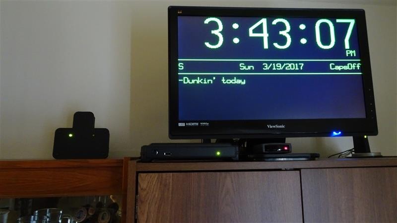
Below is the wireless IR keyboard I bought on ebay. It’s receiver can be seen just below the center of the monitor with the red LED indicator. I wired that to my main unit with a short cable. |
|
I finished the Big Clock in Sept. of 2015 and we have been using it ever since. Then in Feb 2017 I did another project, the “Large LED Matrix Clock” which I write about below as the next project. I had given the LED clock WiFi capability so that it could go out on the web and get the exact time from NIST to set itself. When I was working on that, it became obvious that I should give Big Clock the same capability. In March of 2017 I designed a small PCB that has a voltage regulator and interface connectors to facilitate a WiFi module. I combined this with another PCB (early “Guest” unit) from eCheckIn development.
This bd. has RJ45 modular connectors running RS485 which connects using LAN cables to what is here the Big Clock. It also has a µC and a switching power supply. Power (+12V) is delivered through the communications cable.
After mocking up all the elements long enough to write the software and test it, I designed an enclosure and 3D printed it. For the cover I designed a panel and used the CNC machine to make it (the enclosure has it’s own section in my “3D Printing & CNC” pages). |
|
WiFi For Big Clock
|
|
Above is the “WiFi For Big Clock” assembled with the cover off in it’s custom enclosure. At the top are air vents with the WiFi module just below. The pushbutton on the left side lets you manually initiate a time fetch. Normal operation is that every 24 hours it goes out on the web to NIST to get the time.
It then sends a formatted string over RS485 to the “Big Clock” which uses it to update the RTC. It also puts an “S” at the extreme left of the date line signifying “Sync”. If the Big Clock does not see another update string within 25 hours, it changes the character to “N” for “No Sync”. It remains “N” until a new update string is received. |
|
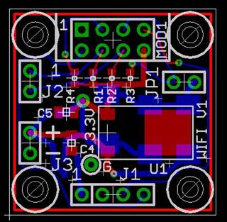
Little 1 in sq. WiFi interface bd. I designed for this project and probably future ones. |
|
Large LED Matrix Clock |
|
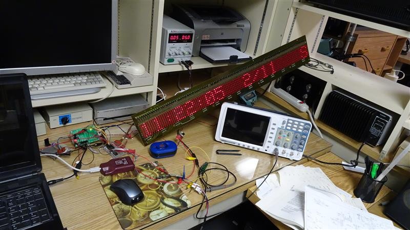
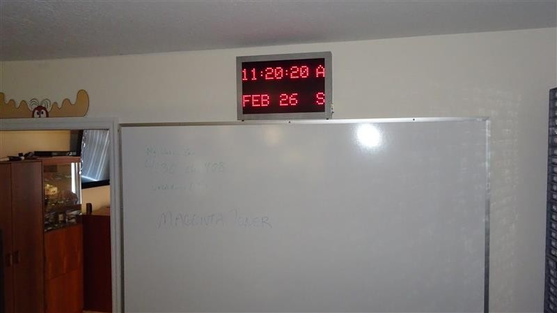
The WWV clock in the lab did not reliably set itself and often has the wrong time. Florida is just too far away from Ft. Collins, CO to get a decent signal. So, I decided to make a wall clock that sets itself using WiFi to go to NIST and get the time. Also, I’d been hoarding this long LED Matrix PCB for decades. It just has the LEDs, column drive transistors and shift registers. I planned to put it above my white board where the old WWV clock was mounted.
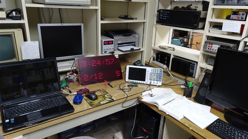
The problem was that I didn’t have one long piece of red plastic filter material to put in front of the LED matrix. What I did have in stock was a fairly large rectangular piece. Using the scroll saw I cut the bd. in half and used little straps I made from scrap PCB material to put the halves one over the other. Now I had a 2-line display. I did have to tack on wires to get the signals from the top to the bottom, but other than that it worked great!
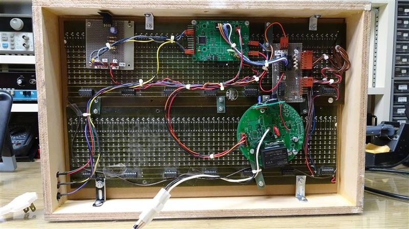
Years ago I had hand-wired a bd. which has source-drivers for the LED matrix rows. Recently, I had hand-wired a WiFi interface bd. (which I later did a PCB layout for to use in the WiFi For Big Clock project). I also repurposed a power supply bd. from my street light controller design job for the AC to 12V supply (round PCB in photo). Onto that I tacked a tiny 5V switching regulator demonstrator bd. from National that I’ve had around for years. The last element was one of my “Dispenser” bds. from my cat food dispenser. It has the µC, RTC, backup battery, 3.3V regulator and plenty of I/Os to bring it all together.
This became a parts-bin project. I didn’t have to buy one thing! In the photos you can see how I started development with the one long LED matrix bd. When I had that going, I cut it in half and made it two rows. There’s a small control panel on the side for status LEDs and a pushbutton. Pushing it quickly turns off the LEDs or if you hold it down 5 seconds it initiates a time fetch. Normally, it goes out to NIST for the time every day at 1pm. The “S” is displayed when the unit is in sync, if not it shows an “N”.
I built the enclosure out of wood. I used the CNC in kind of a manual mode to make a very small groove in the frame pieces that the edges of the filter slide into. Since we didn’t want the wood-look, Linda painted it with a very nice gray hammer-tone finish which looks great on the wall. |