
|
Cat Food Dispenser |

|
You can find our cat Squishy sitting at her bowl precisely at 10AM & 3PM waiting for her dry food. Nothing makes her happier than getting her food on time. Also, my wife likes to see Squishy fed on a regular schedule. Although this is just a concept exercise, I like to give the final design a consumer product name. The obvious name: “Pussy-Pleaser”.
Now in a large corporation, for some reason, the Marketing department would have final say on the name, not Engineering.
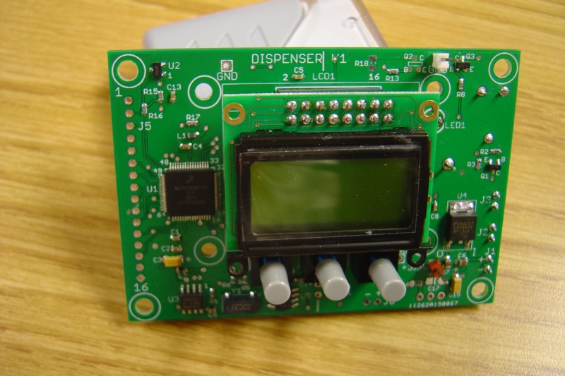
The goal was to be able to set the unit to vend dry cat food at several programmable times throughout the day. To allow this, there is an LCD on the front panel with 3 “soft switches”, i.e. switches whose functions are defined by software. These buttons take on the functions labeled above them on the bottom line of the display.
The main screen shows real time on the top line. The bottom line labels the left button “MENU” and the right button “ON/OFF”. Pushing the right button on this screen toggles the label between ON and OFF, and the bipolar LED to the right of the display is green when the unit is ON and goes off when the unit is OFF. This ON/OFF status determines whether the unit will “vend” when it reaches programmed vend times. The LED allows you to check it’s status from across the room without looking at the LCD.
The “MENU” button takes you through a series of choices “Program?”, “SetTime?” & “VendNow?” (see Owner’s Manual).
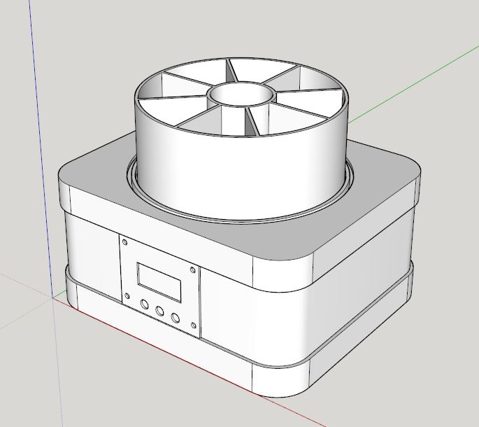
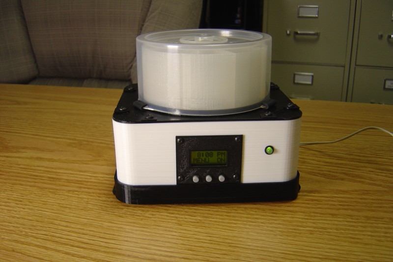
Photo 1 shows the unit completely together. On top sits a round Food Bin with 8 somewhat triangular compartments. At vend time, it rotates clockwise until the next compartment lines up with the opening in the top plate, through which that compartment’s food falls through the unit’s internal pipe and exits out the bottom left.
I’ve used a transparent polypropylene cover from a CD-R package as an overall cover for the translucent Food Bin. The tabs on the cover are held down by a “Top Surround” which pressure fits around the entire top of the unit.
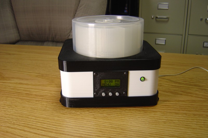
Photo 2 shows the “Top Surround” removed leaving the Food Bin and the transparent cover.
Photo 3 has the cover removed and we see just the Food Bin on top.
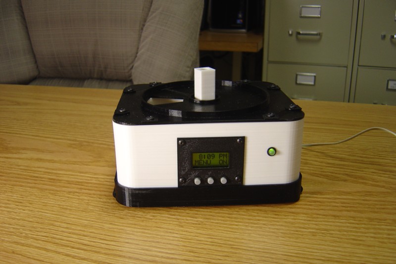
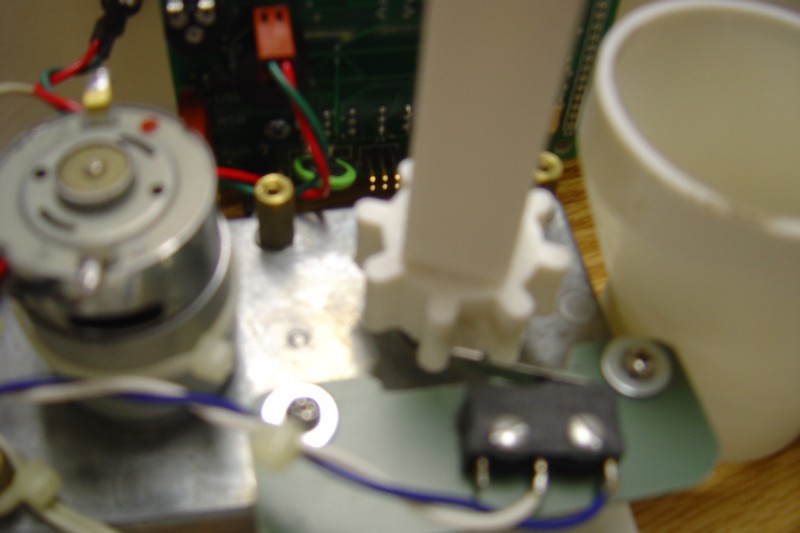
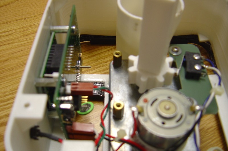
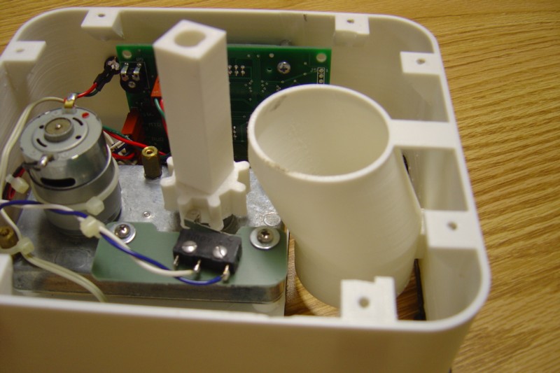
Photo 4 shows the Food Bin removed, leaving only the Rotator protruding from the unit. The food bin has a square hole in the center which mates with the square exterior of the Rotator.
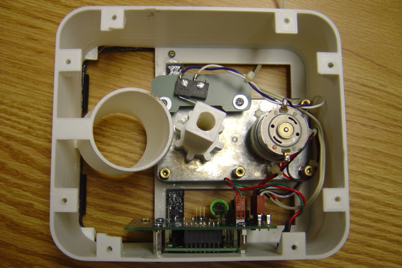
Photo 5, with the unit is taken apart, is a view from above where you can see how the Rotator fits over the output shaft of the gear reduction motor. It actually has a D opening that matches the output shaft so it can’t rotate at the junction.
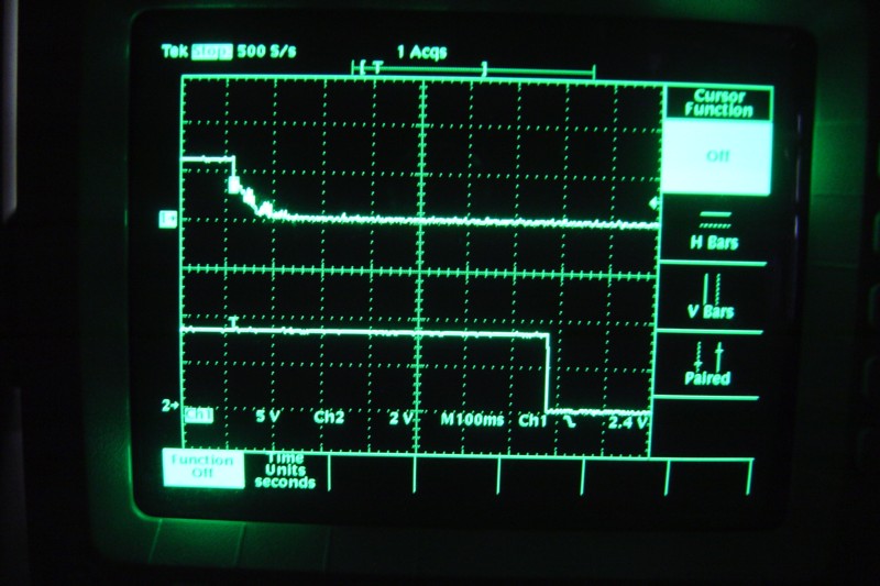
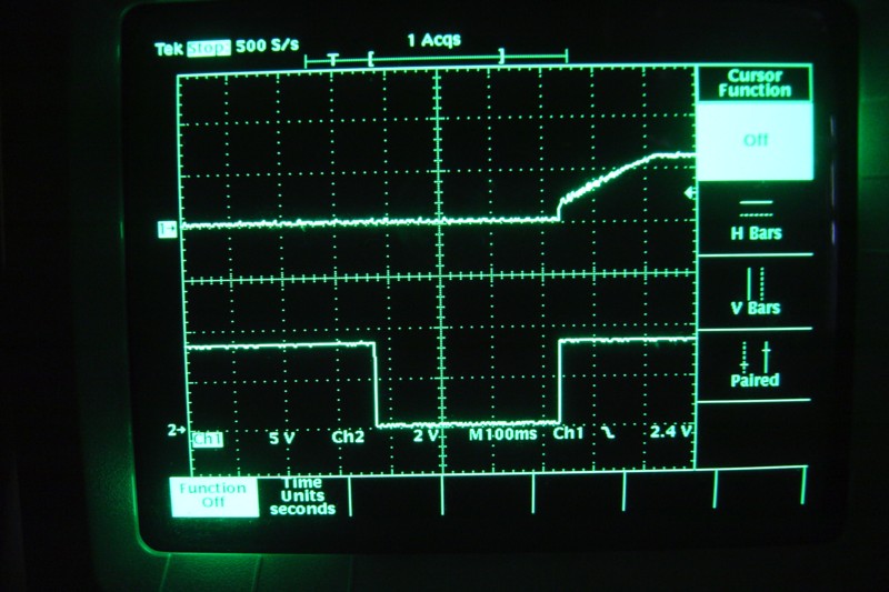
You can also see the microswitch mounted on a piece of PCB material above the motor. The switch’s lever gets pushed by the 8 “bumps” on the bottom of the Rotator. Careful alignment has the switch go from actuated to released just as the next Food Bin segment is aligned with the chute opening. The microcontroller sees this transition and turns off the motor. The entire operation takes approx. 950 msec.
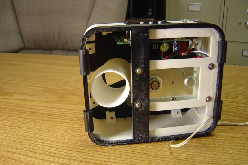
On the back of the front panel you can see the PCB which was designed specifically for the Dispenser.
The unit uses 8 different 3D printed parts:
1) Food Bin sits on top under clear cover 2) Top Surround which you slide up & off to get at the cover & bin 3) Spacers are little tabs/washers under the Top Plate’s screws 4) Top Plate has the round area where the Food Bin sits & rotates 5) Enclosure is the white ABS bulk of the housing, has integral curved chute inside. 6) Bezel has LCD window opening and holes for pushbuttons, all matching the PCB layout. The screws holding it on go into standoffs on the inside which also support the PCB. 7) Bottom Surround provides the base structure and solid crossmember to support the motor. 8) Rotator has a D shaped hole all the way through to mate with the motor’s output shaft. At the bottom it has a section with 8 “bumps” which actuate the microswitch. The rest of the length is a square which matches the center of the Food Bin which slides down on it.
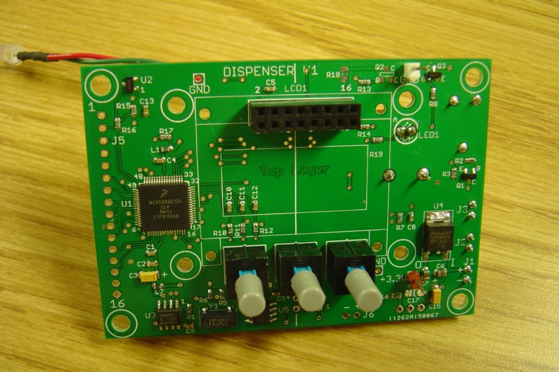
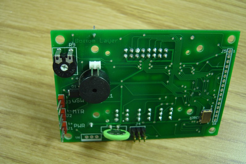
The PCB incorporates a Freescale MC9S08QE128 µC in a 64-lead LQFP package. A bit of an overkill, but I put in an expansion connector with lots of additional I/O so I can use this PCB for other projects, especially ones that need a small LCD interface.
Also on the board is a RTC (Real Time Clock) with a 10-year lithium backup battery, a ridiculously large I2C EEPROM (of which I am only using 8 bytes to store vend times & flags), along with buttons, motor drive, bipolar LED connector, etc.
Update: The Nov 2016 edition of “Design News” (and on their website) featured the Cat Food Dispenser in their “Gadget Freak” section. See the “Electronics - Published Magazine Articles & Early Electronic Projects” section of our website.
|
|
5 |
|
Electronics |
|
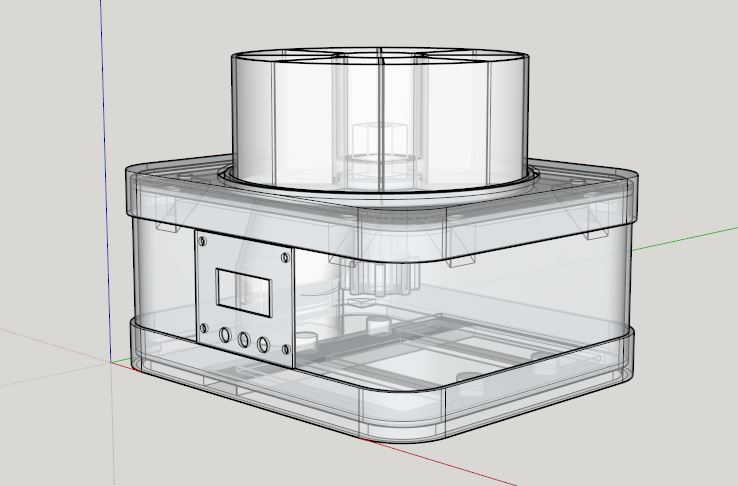
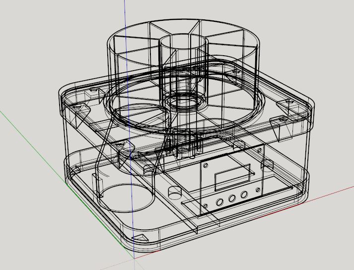
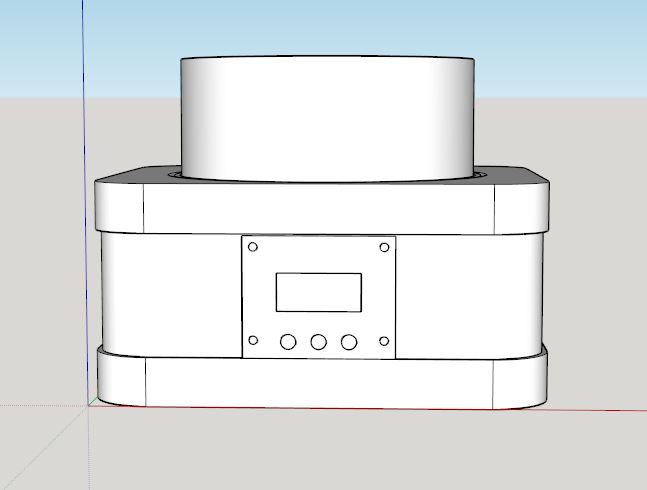
I put together a composite of all the SketchUp drawings. Here are some of the more interesting views. |
|
Electronics & Maker Projects (page 3) |

|
1 |
|
2 |
|
3 |
|
4 |

|
Side View |
|
Bottom View |
|
Motor (top trace) and µswitch (bottom trace) during a vend operation. |
|
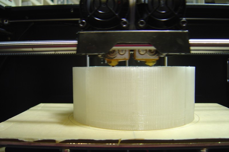
Food Bin being printed. |
|
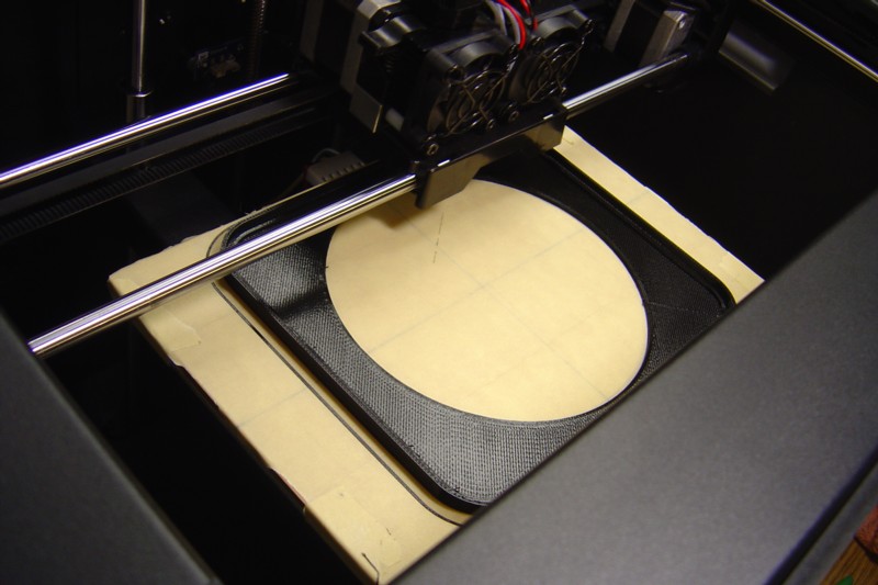
Top Surround being printed. |
|
5 |
|
Internal Views |