|
Ryobi Battery Adapter |

|
Electronics & Maker Projects (page 4) |
|
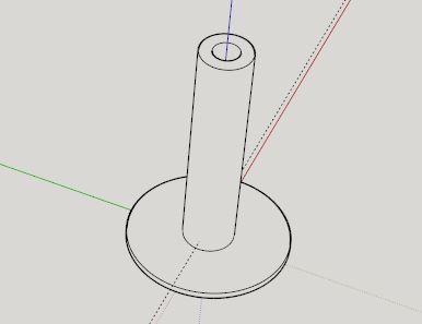
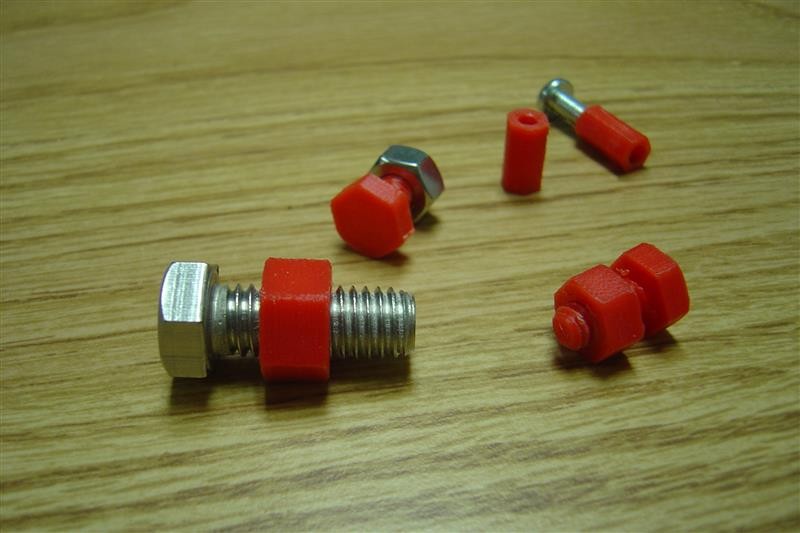
Hardware From McMaster Files |
|
Shop Styrofoam Wall Hanging Flange |
|
K&L Tools Illuminated Sign |
|
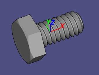
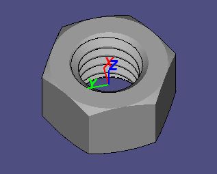
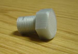
I read online that the McMaster-Carr website has 3D CAD files of hardware. I downloaded a few STEP files, converted them to STL using “FreeCAD” and was able to print them! In the end I found it necessary to use a tap / die to get the threads truly useful, but what a great facility. The one in silver/gray I made much later and ran it through SketchUp to make it shorter. |
|
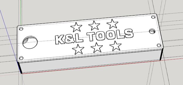
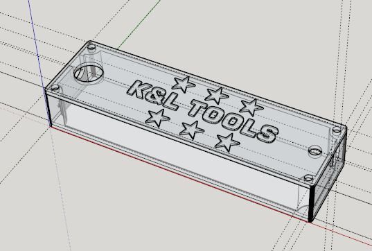
This started as nothing more than an experiment in using dual extruders to have two colors on the same layer, here through the entire thickness. I used black with clear for the lettering. Well, in reality it was kind of a failure, as so much black was dragged around that it put random lines through the clear area. However, the end effect was kind of artistic, reminding one of cracked glass.
I’d been hoarding this AC powered Harbor Freight LED worklight that I never use because it only puts out a pathetic amount of light. I decided to use it as a backlight and made the top & bottom angle pieces to fill up the light’s opening. Linda thought it looked great, so I mounted it above the shop bench with magnets. |
|
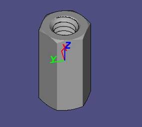
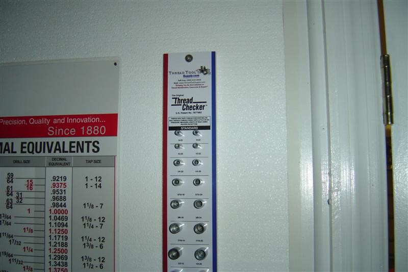
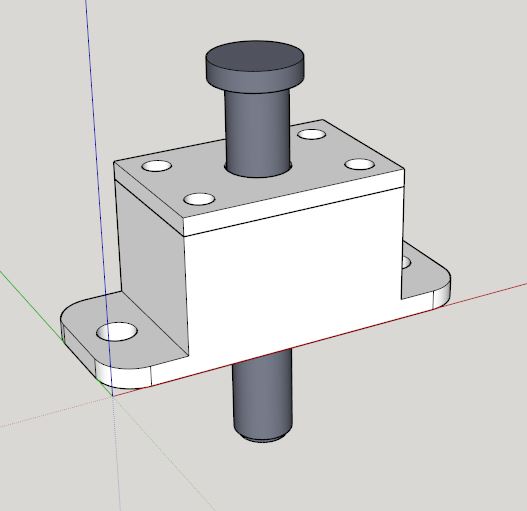
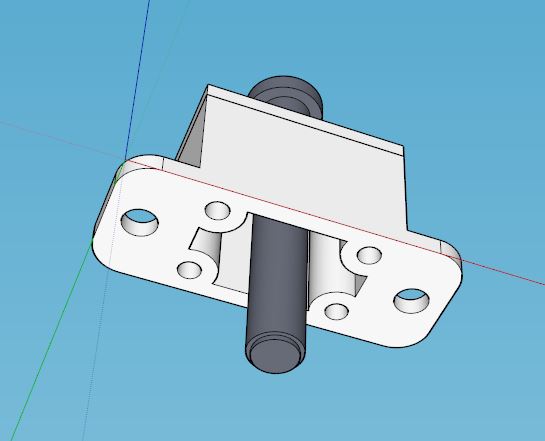
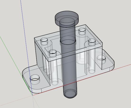
I ordered this huge “Thread Checker” board, the kind you might see in a hardware store. It’s 3” wide and 39” tall. I intended to hang it on the shop’s styrofoam walls.
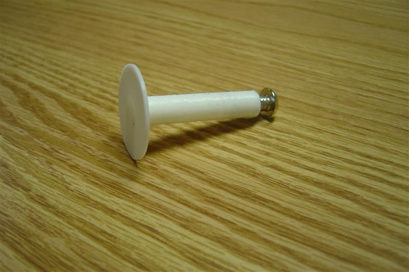
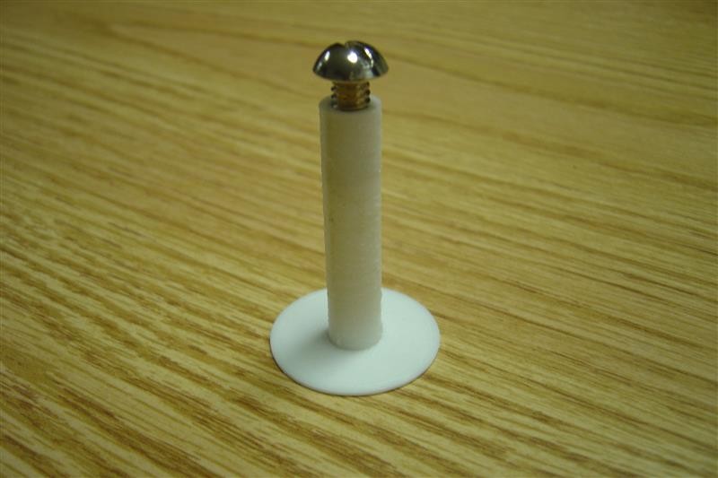
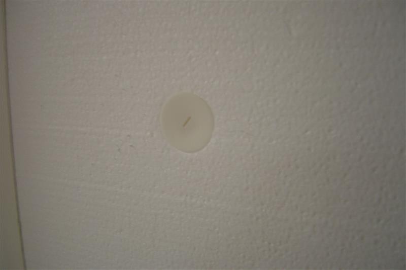
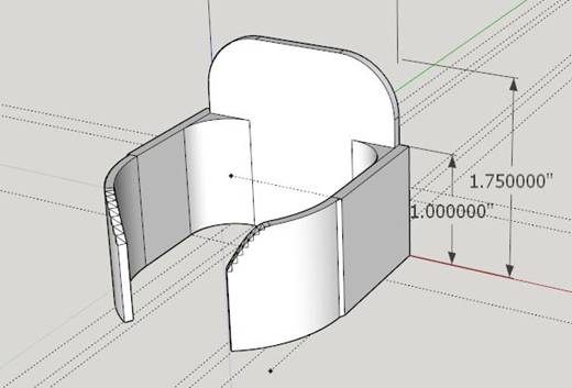
The checker is a bit heavy, so I designed this flange where you poke a hole in the styrofoam with a screwdriver, then insert it’s shaft. The large flat base keeps it from pulling through, spreads the force and provides stability. Inside the shop, I attached the checker with 1/4”-20 screws into threads in the shaft that I created with a tap. One of the 3 screws can be seen in the photo to the right at the top center of the “Thread Checker” board.
I designed in a small slit in the center of the outside flange to allow holding it steady with a small flat blade screwdriver while the screw is being tightened on the other side. You can see the slit on the flange in the photo above this text. |


|
The batteries in my rechargeable Craftsman LED worklight were going bad after many years of service. I was about to open it up and replace them, when I thought about other options. Why not make a power tap adapter for a Ryobi battery and run the light on that? We have 6 Ryobi batteries on a 6-way charger, and they hold a lot of energy. Also, there may be other things that can be powered by these always-present / always-charged batteries.
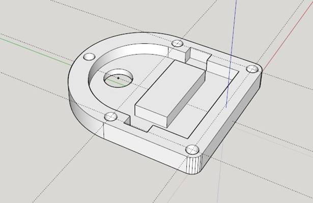
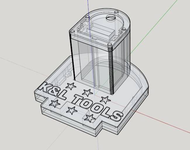
So, I started taking careful measurements of the rather intricate tabs on the tool side which interlock with the spring loaded release levers on the battery side. Having never looked at these closely, I was surprised to see how many tiny interlocking grooves/protrusions were involved. It was kind of like copying a key. I broke the project up into 3 pieces which allowed me to use no support material at all.
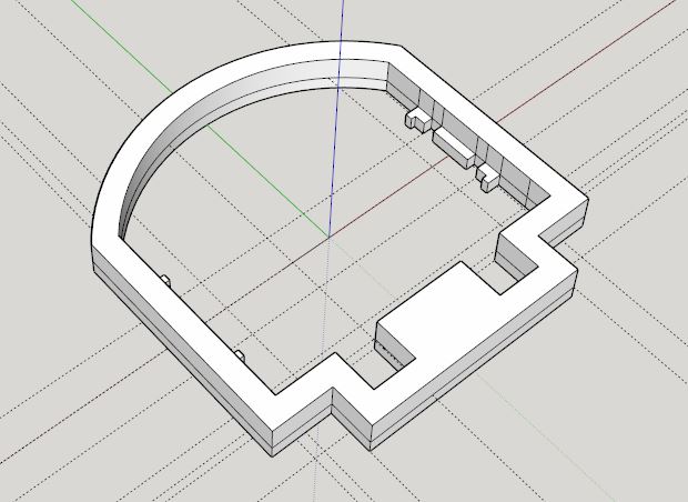
The bottom section (see CAD drawings above) has the interlocking latch tabs and clearance areas for the two rectangular protrusions that come up from the battery.
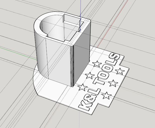
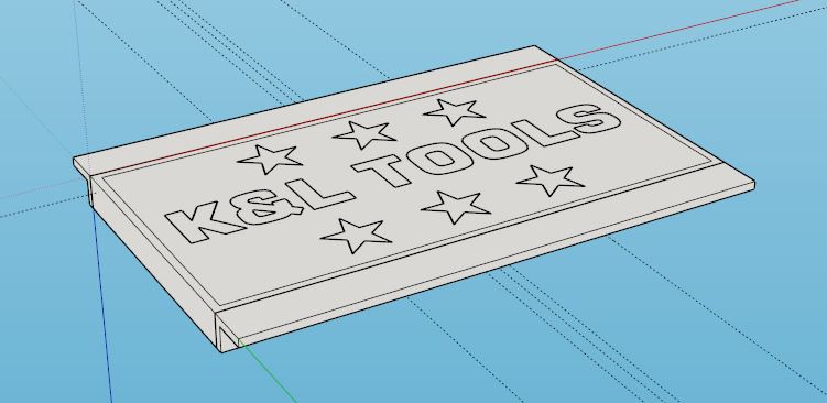
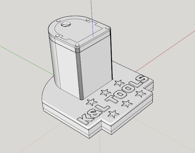
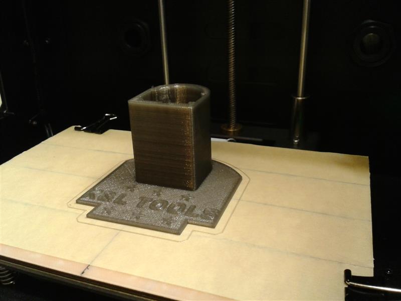
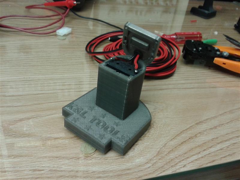
The middle section (seen just after printing to the right) has a plate at the bottom which matches the outline of the bottom section to which it will be super-glued. I also couldn’t resist putting the now ubiquitous “K&L TOOLS” on the face. The D-shaped “silo” has a radius which is an extension of the radius I measured on the battery. At the very top, I had to leave a void where a modified 1/2AA battery holder will get inserted. You can see the black rectangle with wires attached in the 2nd photo. This is the bottom of the battery holder, with it’s spring contacts facing down to meet the top of the Ryobi battery.
After attaching the cable and running it through a rubber grommet in the hole in the top section, I used 5 black sheet metal screws to hold it on. To allow using the power for other things, I terminated the cable with a 2-way .093” molex connector.
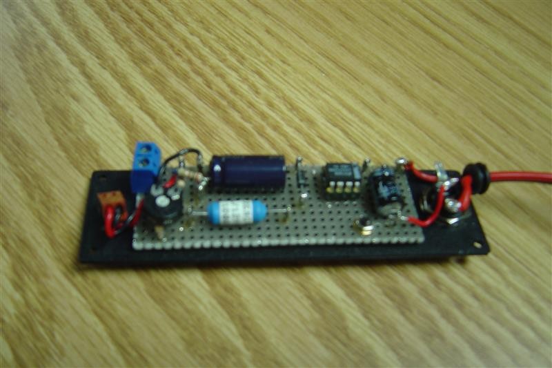
I took apart the worklight and found it has 3 x 1.2V rechargeable batteries. So now I have 18V available but need 3.6V to run the light. This is where part 2 of this project begins. I found an old switching power supply prototype which I had hand-wired many years ago. It was fixed at 5V, so I made a few changes and made it variable. I adjusted the pot for 3.6V.
Now all I needed to do was design a simple enclosure for the switching supply. Actually, this is what I thought I’d be doing with the 3D printer when I bought it, creating panels or entire enclosures to house my electronics projects. Of course, the 3D printing itself became so engaging that I’ve been making all sorts of things, electronics related and otherwise. Anyway, for the first time I was not laying out a PCB to fit into an enclosure, I was designing an enclosure to wrap around an existing board!
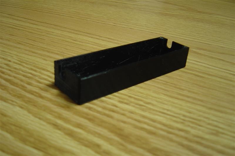
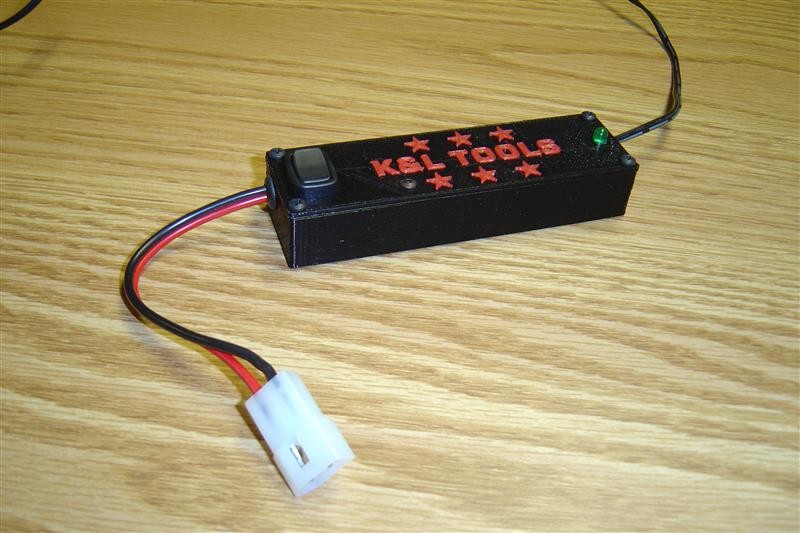
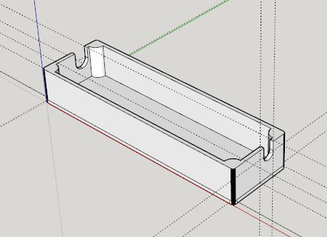
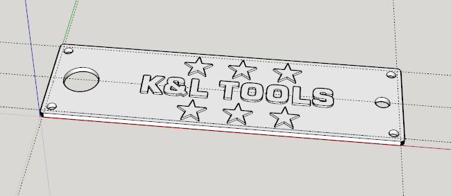
I made the top panel the main focus (see CAD drawings below). It has a hole for the switch and LED power indicator. The circuit board attaches with one screw. Wires exit each side through rubber grommets. The grommets slide into slots made into each side of the enclosure’s bottom, allowing easy assembly / disassembly. I also took this opportunity to once again experiment with dual extruder / two color 3D printing to put red lettering on the black top panel.
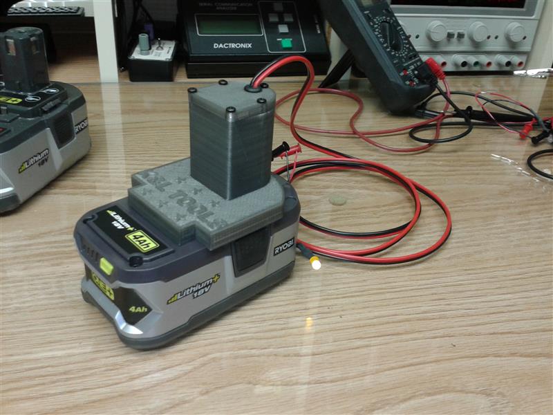
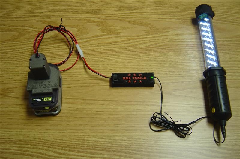
So now I have the whole chain. The Ryobi power tap which snaps on the battery, the switching supply to give me the voltage I need with decent efficiency and the output cable is the original charger cable which plugs into the bottom of the worklight.
When I removed the worklight’s batteries, I changed it’s wiring so the charge jack now directly powers the light. The last photo shows the whole thing with the light on.
|
|
Bottom Section |
|
Middle Section |
|
Top Section (flipped) |
|
Composite |
|
Electric Razor Holder |

|
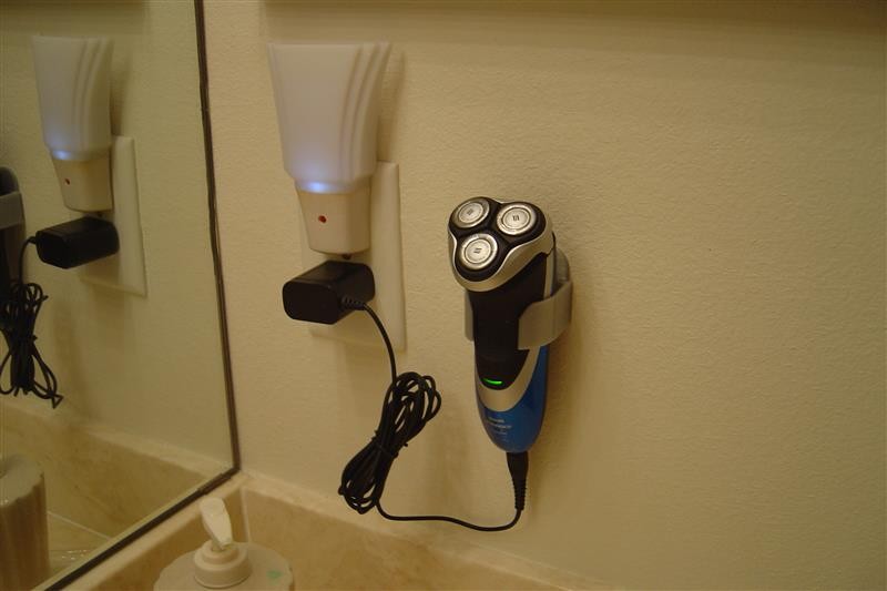
Once I got used to using the electric razor Linda gave me for Christmas I ended up shaving more often since it takes so much less time! However, I would just leave it sitting on the sink top being charged. Why not design a holder/bracket to mount it on the wall? |
|
Reception Window Latch |
|
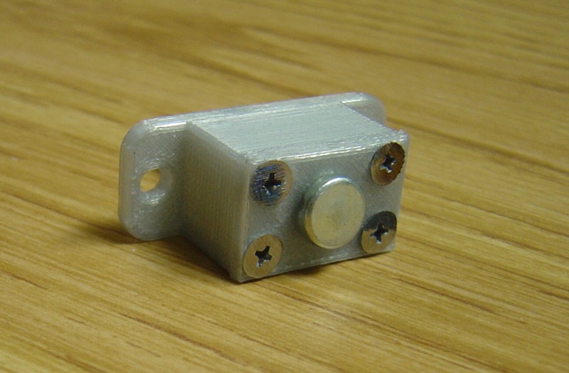
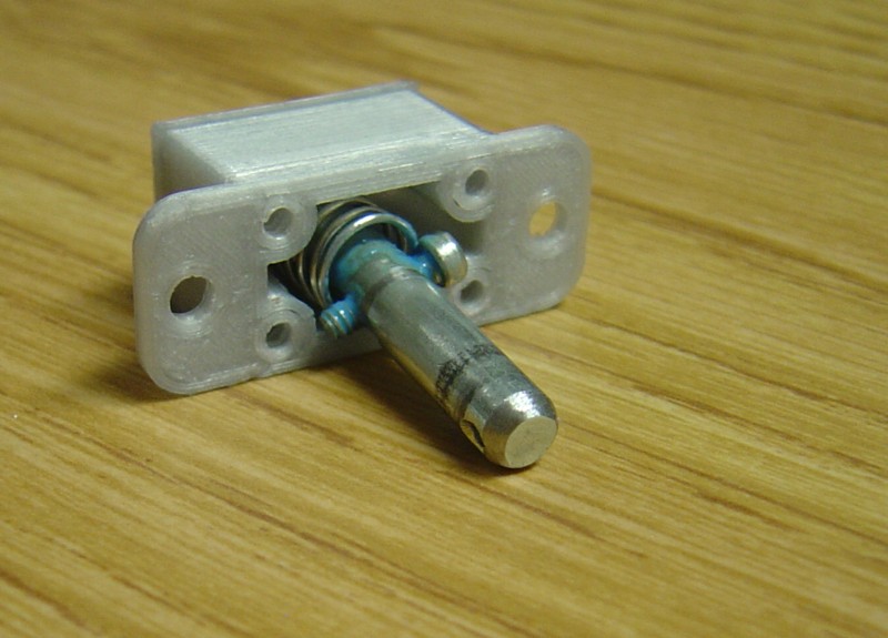
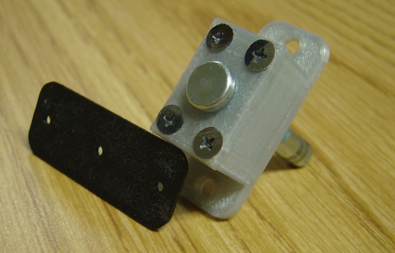
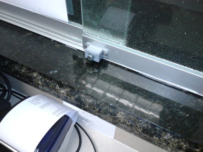
Linda was getting tired of patients coming into her office and throwing open the reception window. So, I designed a latch by spring loading a clevis pin.
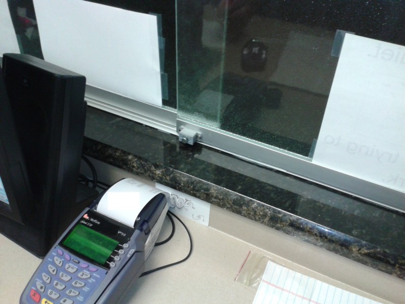
The pin protrudes all the way through the inner window’s aluminum channel / frame, through the gap between windows and ends halfway into the outer window’s frame. This makes it impossible to open the window. To open it, just pull out on the clevis pin until it clears the outer window’s frame and slide it open. When pushing the window closed, the clevis pin snaps into place to latch.
Below are photos of the latch. The black plate was a template I used to accurately drill the holes in the aluminum frames. At the bottom you can see it all in place. |