
|
Electronics & Maker Projects (page 8) |
|
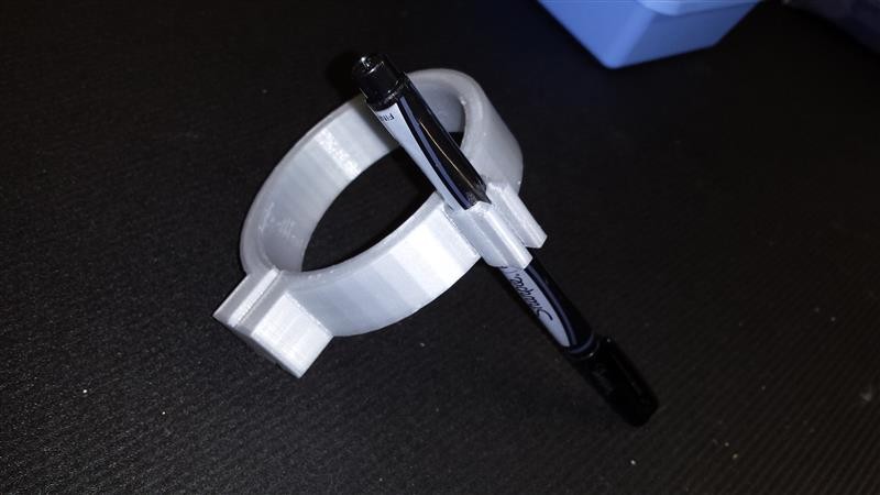
Pen Holder For CNC (3D Printing) |
|
Dial Indicator Holder For CNC (CNC) |
|
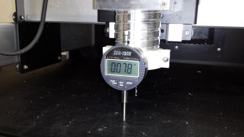
Another thing I had mocked-up for one-time use was a bracket to hold a Digital Dial Indicator. I used this to get an idea of what kind of variation in bed height I might have to adjust or compensate for. I had used a right angle bracket clamped to the router holder, which was pretty crude. I knew I would eventually make a real bracket.
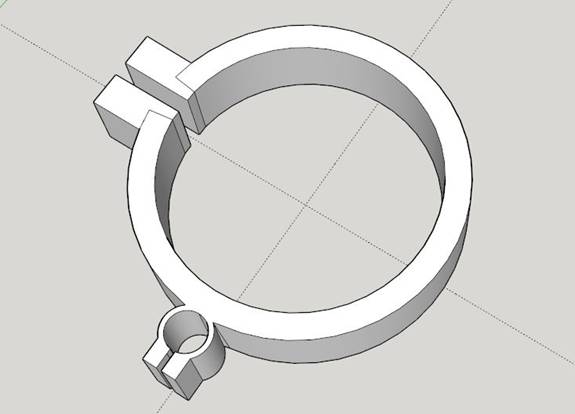
After making the pen holder with 3D printing, I was determined to do this project with the CNC itself. When buying the Shapeoko3 I also ordered some of their materials. One type was the HDPE 3” x 5” plastic blocks. It’s white in color and really strong. Starting with the SketchUp Pen Holder design, I modified it to create the Dial Indictor Holder. I used SketchUCam to specify cutting parameters and generate the .nc files.
This is one of the more difficult aspects to CNC work as opposed to 3D printing. With 3D printing, I have one nice workflow, where I design in SketchUp, import .stl files into Simplify3D which generates .x3g files for the printer. But with CNC, I’m finding I need to switch to all sorts of programs both for design and CAM depending on the project. Also, I really don’t want to abandon SketchUp, as becoming proficient at it required climbing a rather large learning curve.
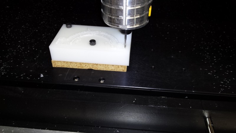
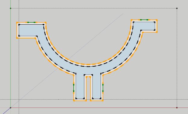
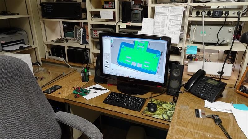
The HDPE blocks were not quite big enough, so I broke it down into a front and rear piece. The top screen shot shows the design in SketchUp, with the orange outline indicating the cuts added with SketchUCam. The little green areas show “tabs”. These are places you specify to not cut all the say through. This keeps the piece you are milling steady at the end, otherwise it would free up and rocket out. When it’s done, you just cut through these tabs with a Dremel.
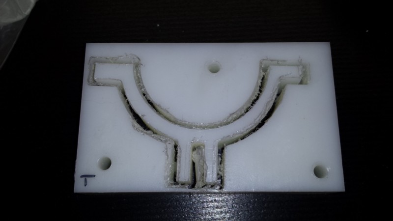
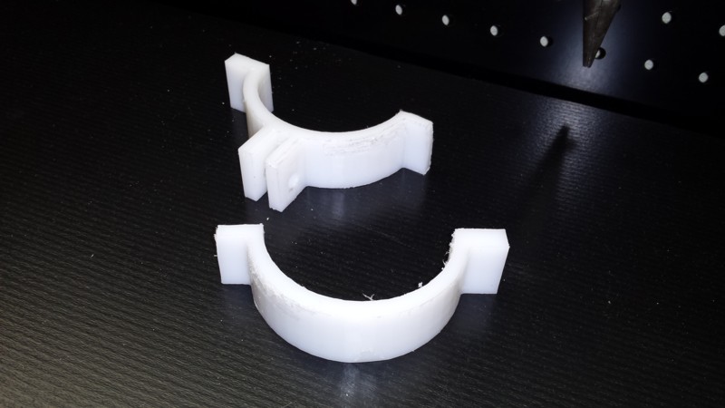
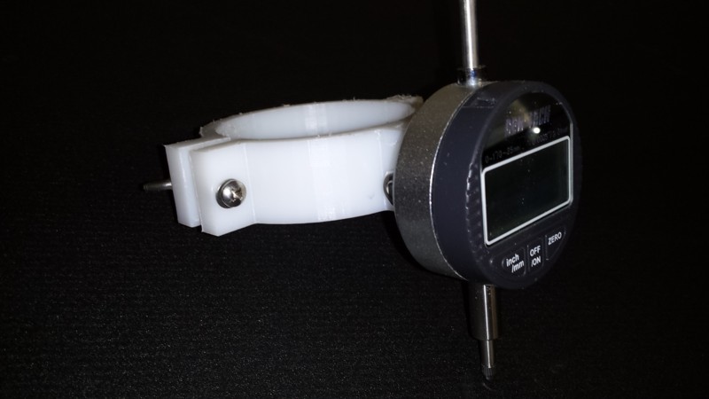
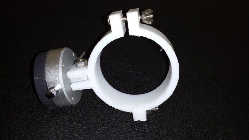
In the photos you can see the two pieces then the whole assembly. Overall the cuts were very nice and crisp. However, there were areas where the surface is kind of “frayed”, for lack of a better word. I need to see what caused this. My first guess is that the cut chips or strands of plastic wrapped around the endmill for a short time, kind of cutting with plastic and melting. Will have to do more HDPE experiments and reading. But, overall it came out nice and is solid as a rock.
|
|
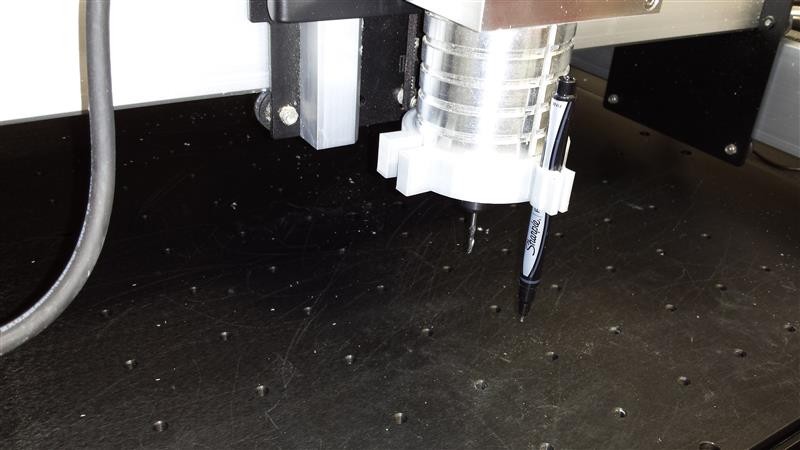
When making name badges on the CNC, I was using precut 1” x 3” material. Since I was not having the machine cut the outline, it was important for it to start out perfectly aligned with the x-axis so the text would be straight. To do this, I put down some tape and used rubber bands to secure a fine point Sharpie to the spindle motor. Then I used the jog controls in Carbide Motion to lower the pen to the tape then move it along the x-axis with fast jog.
This gave me a perfect line that I used to place the edge of the badge. I could see the general usefulness of this technique, so later I decided to actually make an official pen holder. I decided to go with 3D printing but was already planning the next variation to be done on the CNC itself (next project below).
It really came out nice, and so far I haven’t even needed the provision for screws to tighten the pen clamp and large clamp as the fit was perfect.
|
|
WiFi For Big Clock (3D Printing & CNC) |
|
The main tale of “WiFi For Big Clock” is in the “Electronics - Articles and Projects” pages. That’s because I consider it more of an electronics project, although I did put a lot of effort into making the custom enclosure presented here.
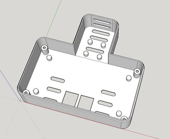
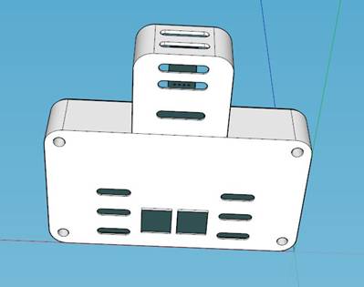
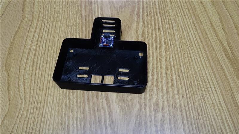
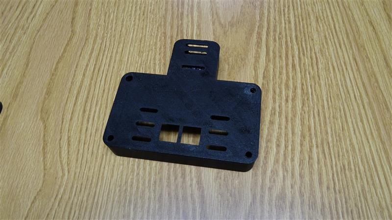
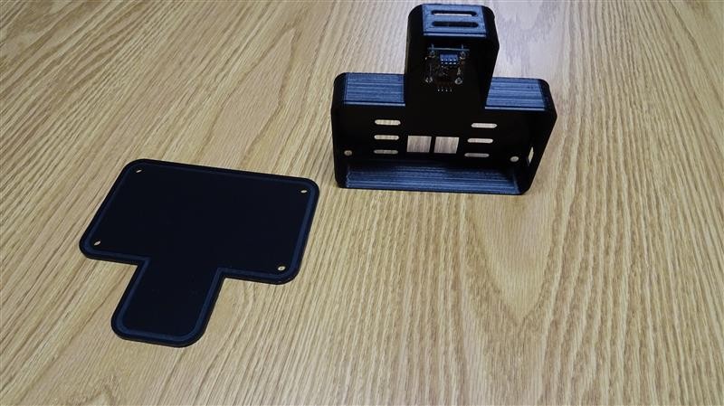
I wanted the WiFi module up high since it has a PCB antenna, and I wanted the RJ45 jacks for the network cable low to let it exit nicely and not topple it over. The rectangular opening on the right side is for the programming connector to allow updating software without opening it up.
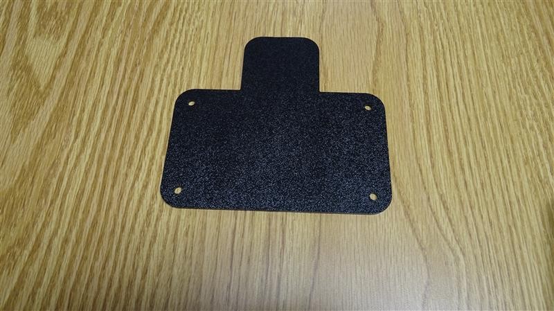
I made the main part of the enclosure with 3D printing and the cover or lid with CNC from a sheet of textured ABS which I’ve hoarded for years. |
|
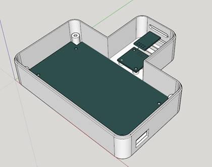
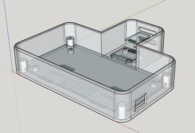
3D printed main housing CAD views |
|
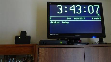
Finished project. See “Electronics - Articles and Projects” pages. |
|
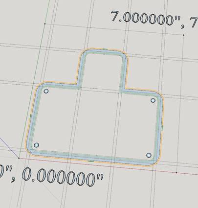
Working on enclosure design. |
|
main housing done |
|
being “printed” |
|
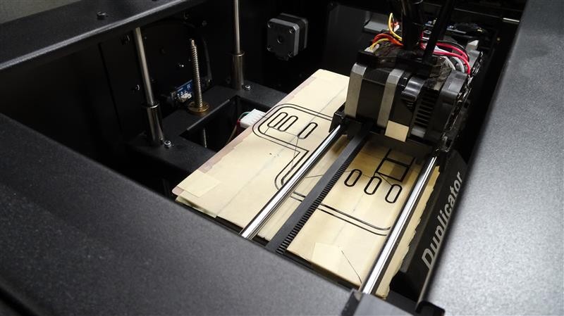
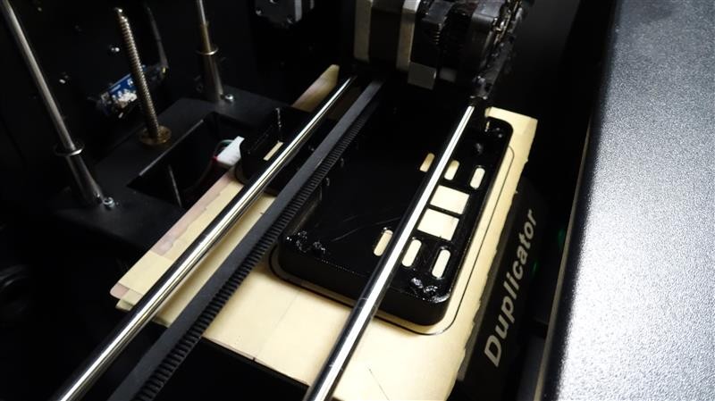
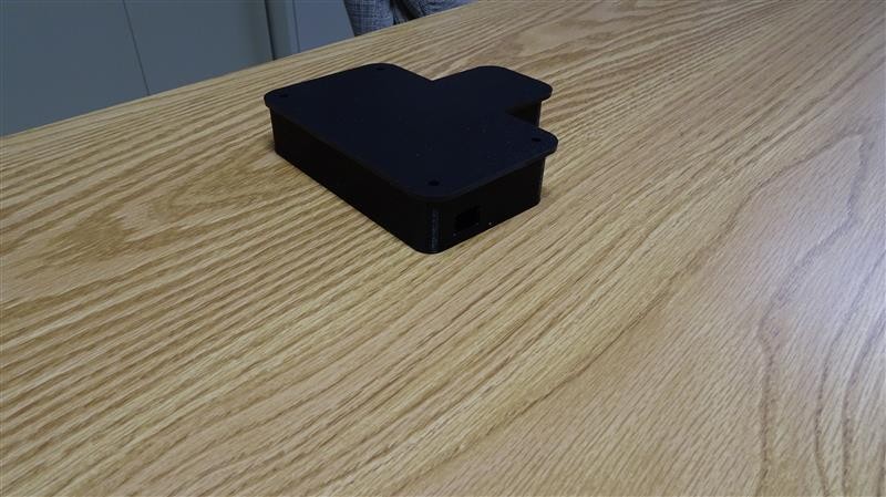
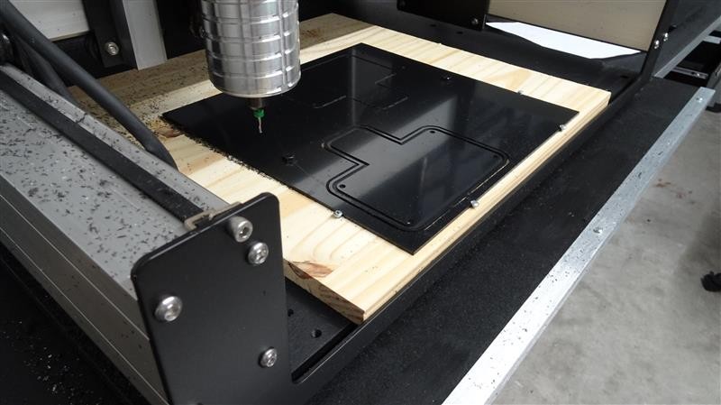
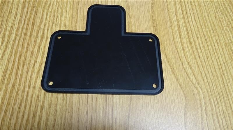
The cover was also designed in SketchUp, where I used SketchUCam to create the toolpath .nc files. These are the color lines on the drawing. At right is the cover being CNCd. In the photo under that you can see that the back of the cover has a groove all the way around. The top lip of the enclosure fits in that groove to firmly couple them. |