

|
Electronics & Maker Projects (page 9) |
|
PCB Milling Experiments (Electronics, CNC) |
|
When I was looking at CNC machines, the fork in the road was the ability to mill PC boards. The tiny, expensive “Othermill” was optimized for making your own PCBs. However, it’s so small it wouldn’t be good for much else. Today’s reality is that you can design a board, send the files off to China, and in about 3 or 4 weeks get them back. They are amazingly cheap and nearly perfect, with plated through holes, solder mask and silk screen. Back in the 20th century, prototype PC boards were so expensive that I rarely ordered them for hobby projects. At work or for commercial purposes, you could of course justify the expense as part of the product development process.
This explains all the projects where I did point-to-point wiring. Well, I’m too old for that now, so I’m happy PCBs are cheap. But, they do take time because they are usually made in China. Even if it seems like you’re ordering from a US company, if it’s cheap they’re probably just an intermediary putting together files into huge panels which they send to China. At most they might depanelize here.
These are the factors I had to think about when deciding on a CNC. Due to the cheap PCBs you can order, I moved milling my own down the list of importance in the selection process and ended up getting the Shapeoko3 which is mid-sized and very general purpose. In the back of my mind, though, the attraction of being able to think of an idea, design the electronics, layout the board, make it on the spot and then assemble it still lingered.
The happy median would be to send out any serious boards but have the ability to mill small, simple boards in-house. I have lots of boards with µCs on them left over from various projects. I always build in extra connectors for unused I/O lines for future use, since you end up ordering multiple copies when you do these bargain orders. So what I usually need is just an interface, voltage regulator, connector adapter or maybe logic level converter to take an existing board and adapt it to a new project. Instead of hand-wiring, now it looks like I can mill them!!!
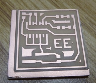
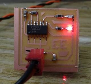
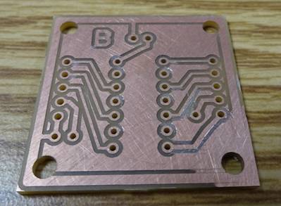
The first thing I tried was single-sided with no holes (Photos 1 & 2). It is just an inverter set up as a slow oscillator, alternating a red & blue surface mount LED. The toolchain I used for this was a ULP plug-in for Eagle but I wasn’t entirely happy with this. I began studying FlatCAM which takes gerber files and lets you define parameters along the way to create .nc files for the CNC. This had kind of a steep learning curve, but now I’m very happy with it. Next I designed an SOIC8 to DIP adapter (Photo 3) which is my first board to have holes.
NetClock 7-Segment (Electronics, CNC, 3DP)
I decided to do a full development project to nail down the PCB milling process. This year so far (2017) I’ve already created the NetClock with LED Matrix display and a WiFi adapter for my Big Clock to set it’s time. So, now I think I’ll make a replacement for the WWV receiver clock we have in the bedroom. It will use 6 7-segment LED displays and of course go out over WiFi for NIST time. I’ll use only parts I have in-house.
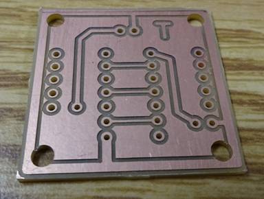
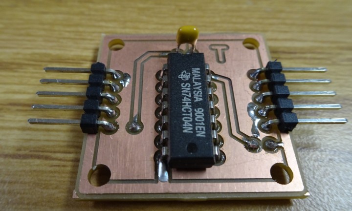
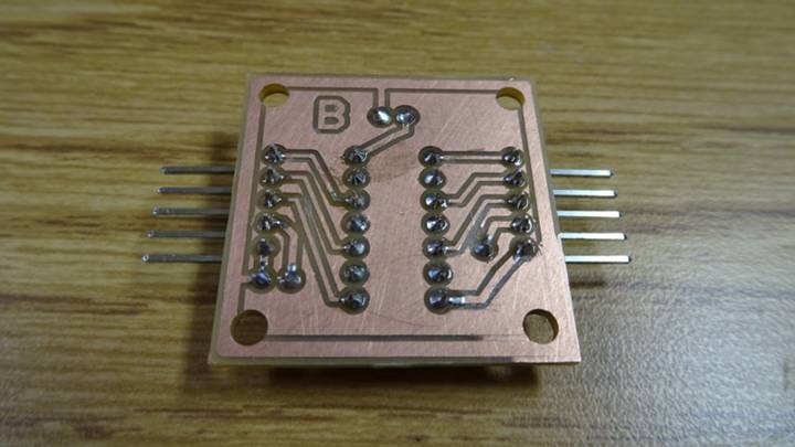
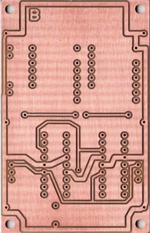
The board I had designed for my Cat Feeder has the µC, RTC (Real Time Clock), 3.3V regulator and plenty of I/Os, everything I need for this project. However, the shift-register source drivers I had in stock need 5V logic. That led me to my next PCB milling project, a simple logic level converter (Photos 4 thru 7). Here was my first try at double-side PCB milling. I used the .125” holes in each corner as tooling holes, so that when I flipped it over to mill the other side I could hold it in the proper location using the shanks of 4 endmills, which are exactly .125” dia. One of the great features of FlatCAM is that it will mill your holes to any size using the same endmill used for copper removal. This means no tool changes which is crucial due to the characteristics of the Shapeoko3.
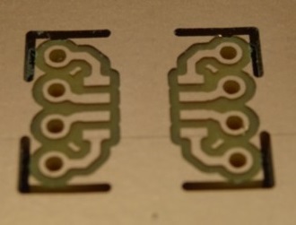
Next was the heart of the project, the LED driver / display bd. I reasoned that trying to make the entire 6-digit clock on one CNC’d PCB was crazy, especially since I was just learning. So, I broke it into 3 identical bds. For my first attempt, I kept it single sided with pads for planned wire jumpers. I used the larger 1206 surface mount resistors because I could use them to jump over traces, minimizing the effect of not having a bottom layer. Then, I got brave and made it double sided. The larger the bd the harder it is to have it perfectly level, so this proved challenging. This bd needed a little xacto-knife fix-up to make it functional. But, having learned a few things from the first two, the third bd worked out perfectly (Photos 8 & 9), ready to go! The CNC mills the track isolation, mills all the holes regardless of size and then mills the entire bd outline leaving just a small tab to hold the material in place which you just snip afterwards. I was quite happy to see this, as the learning curve took about 3 weeks working at it on and off.
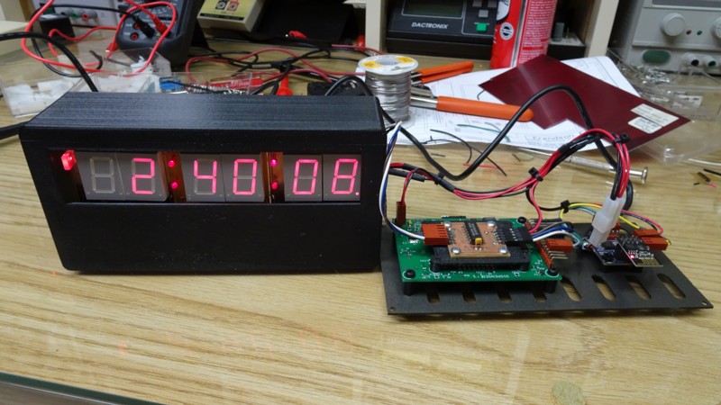
Photo 10 shows all 3 driver / display bds all built, soldered together and working. You can see the single-sided first one I made which ended up in the middle. It has wire jumpers on the back. In the photo I’ve got micro-grabber test leads connecting it to the µC bd and supply. I wrote the software starting with the framework of the matrix display clock and it worked on first power-up, no debugging necessary.
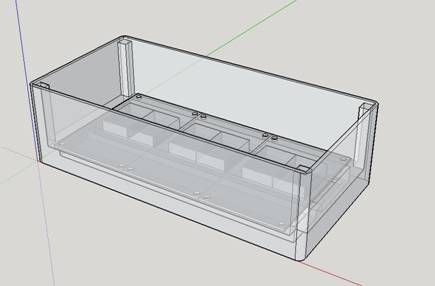
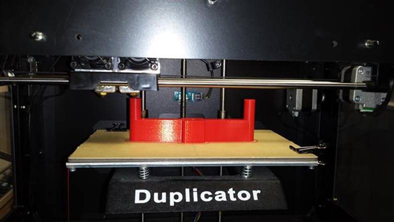
Next was designing the housing (Photo 11 & Video). 3D printing allows me to design the housing to match the electronics, not the other way around as I usually have to do. Internally, I made a pocket for the red filter material to be held in place. I also put in “ledges” at top and bottom for the driver / display bds to screw into, like natural standoffs.
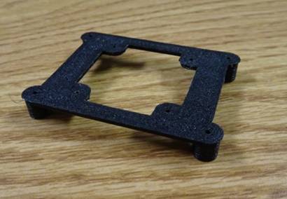
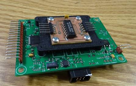
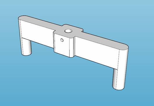
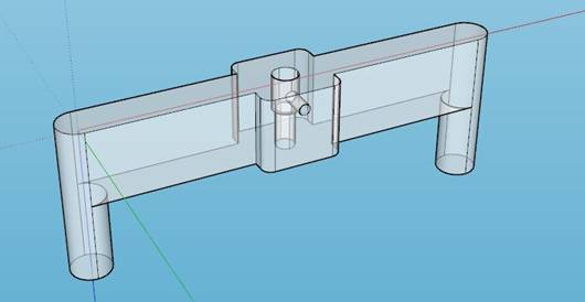
The little logic level converter bd needed a location where it would be out of the way, so I decided to mount it to the µC bd. None of the holes really lined up, so I designed a kind of standoff bracket (Photos 12 & 13). Small sheet metal screws hold it to the µC bd from the bottom and are also used to fasten the converter bd to the top.
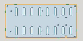
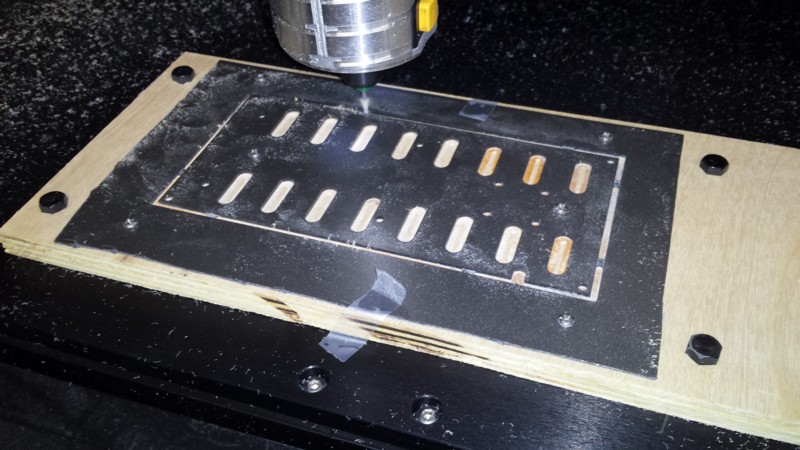
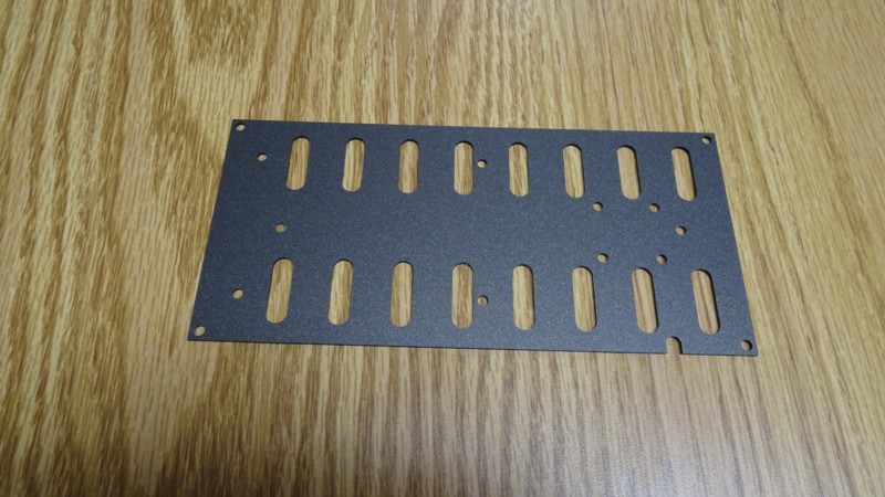
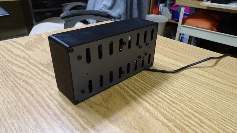
The rear panel for the enclosure was a good candidate for CNC. I had designed the circuitry to keep it simple and use parts I had on hand, knowing this would result in a little bit of internal heat. It was going to need some venting holes in the rear panel. The CNC did a nice job, milling (Photos 14 thru 16 & Video) the overall outline, the vent holes and even all my PCB mounting holes.
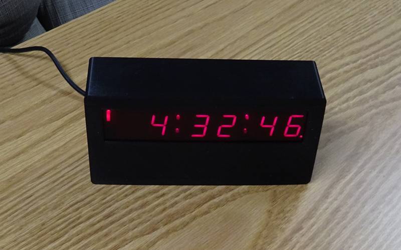
Finally it was time to make the wiring harness (Photos 17 & 18) and put it all together (Photos 19 & 20). The lower right decimal point indicates PM, the upper left corner vertical LED shows that the time is correct because it has updated itself in the last 24 hours. If it can’t get through then that indicator will go out. But, I have a small lithium battery supplying the RTC, so even without sync it will have the right time even if there are power failures.
Well, it turned out to be the perfect project for nailing down a good level of PCB CNCing. Breaking up the display into 3 parts let me learn in an iterative process.
|


|
1 |
|
2 |
|
3 |
|
4
|
|
5 |
|
6
|
|
7 |
|
8 |
|
9 |
|
10 |
|
11 |
|
12 |
|
13 |
|
14 |
|
15 |
|
16 |
|
17 |
|
18 |
|
19 |
|
20 |
|
Various CAD views |
|
Mail’s In! Alert (Electronics, CNC) |
|
I printed this on 2017-12-12. On 2017-09-14 we were in TN running from what was supposed to be a disastrous hurricane, at which time we put a deposit down on a house. Now we have a huge project to get our FL home ready to sell.
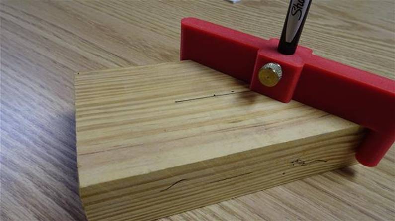
Moving into uncharted waters, I need to build interior walls using 2x4s. I’ve never really done this before, so it’s time to see if any of my skills are going to translate. I ordered a dual axis 360 degree self leveling laser level. I gave it a quick try and it looks like it’s going to be very useful. My thought is to draw a line down the center of a 2x4, hold it up at the ceiling and align it to the laser line. I looked for center line drawing tools and found a concept that I liked. But reading the reviews, I could see the units offered are lacking. Why not design my own?
I put it together in CAD, looking to have it hold a Sharpie “Pen” style marker. I made all the dimensions match the marker and put in a provision for a thumbscrew to hold it in place. |
|
Center Line Marker (3DP) |
|
Remember in the Addams Family, when the mail arrives there’s a whoop-whoop-whoop alarm and Morticia says “Mail’s In!”? (click icon to the right to see a short clip from the show)
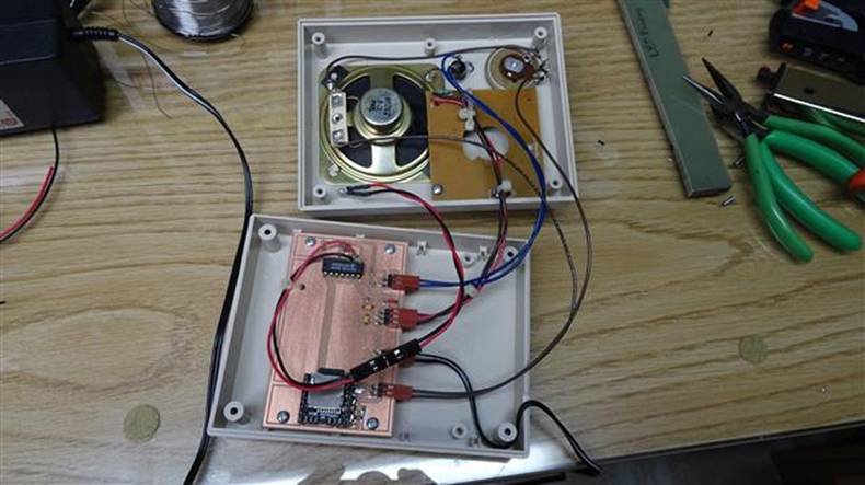
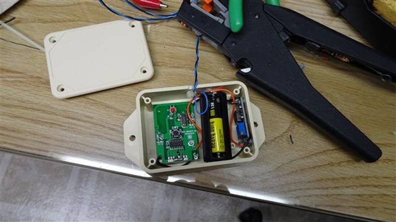
Well, we’re just strange enough to have that too! I used a cheap wireless doorbell from Harbor Freight, found the pulse on the receiver’s PCB which triggers the bell sound (which I disabled), then just used the modified receiver with a short cable to an enclosure where I put an mp3 module, speaker, volume control and a little logic. I designed a PCB to tie it all together and milled it on the CNC. I put the xmtr bd in a small sealed enclosure with a battery holder I salvaged from a HF flashlight. It was first installed in FL, but I have it working now in TN. When the mailman opens the door, we know instantly! It’s a little startling at first, but you get used to it. (click icon to see video of it on the shelf working) |