


|
Electronics & Maker Projects (page 11) |
|
After putting up the deposit for the new house in TN I asked to get the floorplan for the basement. When I got it, there was a lot of ambiguity as to where the HVAC would be located. What I wanted to do was plan the entire basement in 3D CAD. I knew it would be impossible once it was full of stuff top to bottom from the move to try and arrange it physically. Anyway, I ended up designing it twice as things changed. It was also important, though, as the door and window to the back yard had to be placed to match the desired layout.
Looking at the basic layout, the first step was to divide the space between my “shop” and my “lab”. There was a 10ft. opening which looked like a natural barrier. In FL, the shop was in the garage and the lab was it’s own space in the house. Actually, that was going to be my main physical benefit from the new house, bringing them together. Sometimes the shop can get messy and generate dust, so I thought I would put a door between the areas. I wanted it large and to not take up too much space. To address that, I thought of a pocket door. It was no huge leap from there to Star Trek Doors! Why not plan to do that someday. They would just be pocket doors, then if I ever got to the stage where I could tackle the automation, they would be ready.
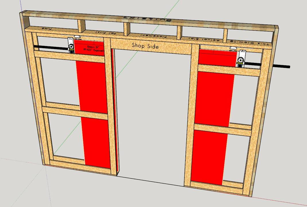
I modeled the basement in 3D CAD, including the wall with the pocket doors. I tried to make the whole plan as detailed as possible. We used the model to build the pocket doors wall and another wall for the Materials Room. Later, I planned the placement of the motor/gear assembly in the wall in CAD before ever building it. |

|
(Electronics, 3DP, CNC, Motors, Gears, Carpentry, Drywall) |
|
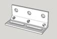
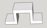
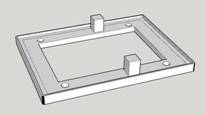
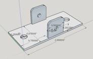
Some of the many small pieces that needed to be created to tie the whole thing together. Listed top row left to right then bottom row:
Aluminum Clevis, (the rest 3DP) Lab Side Console Backplate, Doors Closed µswitch Bracket, Doors Open µswitch Bracket, µwave Motion Detector Bracket, Pipe Bracket, Controller Chassis Front Panel. |
|
Entire 10ft. wall with Motor/Gear/Gear Track assemblies installed. |
|
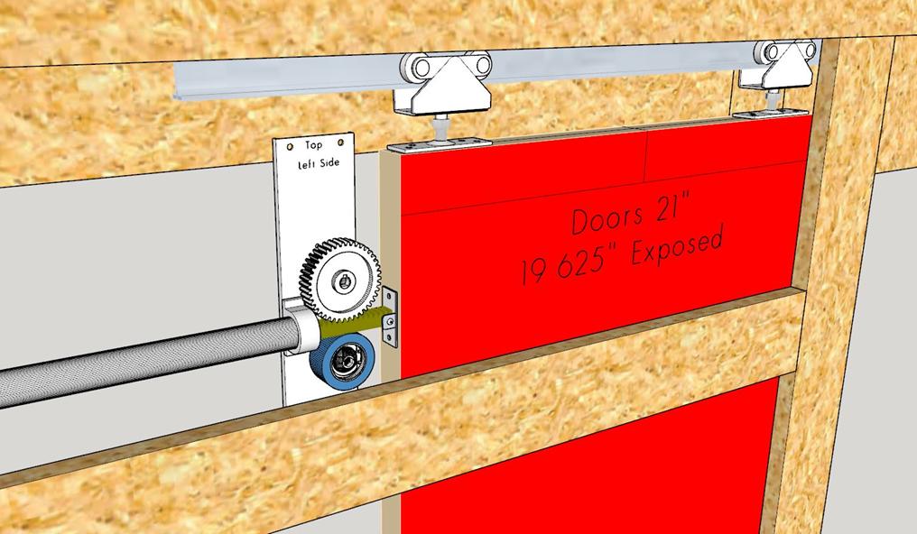
Closeup of the Motor/Gear/Gear Track assy. from the Lab side. |
|
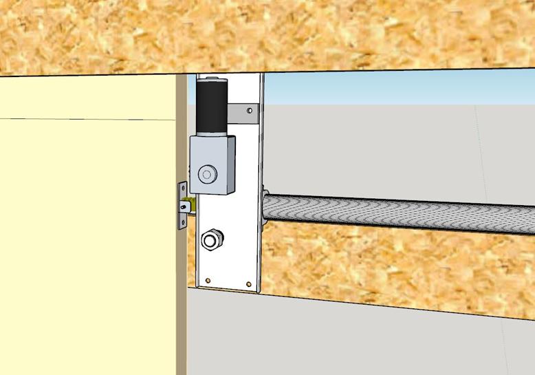
Closeup of the Motor/Gear/Gear Track assy. from the Shop side. I chose this side to make the larger drywall opening for installation & access. |
|
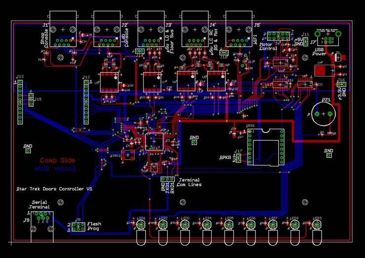
Star Trek Doors Controller PCB Layout |

|
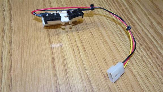
“Closed” µswitchs assy. mounts above doors in center. |
|
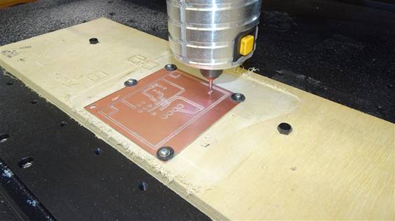
Milling PCB for Lab Side Console |
|
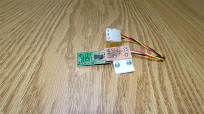
µwave Motion Sensor mated with CNC milled Interface Bd, all mounted on 3DP bracket. |
|
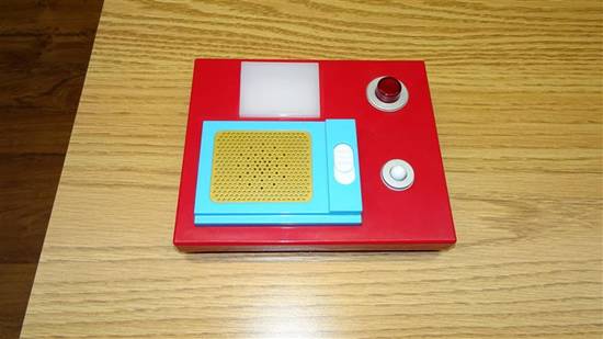
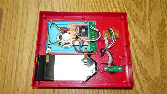
ThinkGeek Star Trek Door Chime. Perfect for my project. I took out all it’s original electronics and rewired with my own PCB (right) |
|
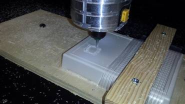
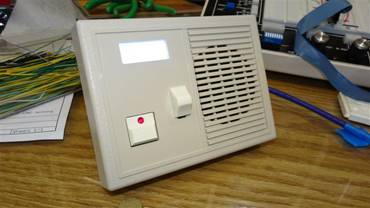
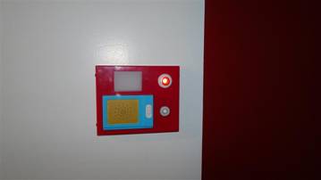
For the Lab side Wall Console, I milled an off the shelf enclosure for abutton/red-LED, a 3-position slide switch (audio hi-lo-off) and an illuminated rectangle (top) which comes on when motion is detected. |
|
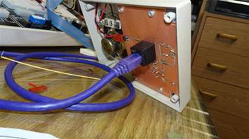
The PCB in the Lab side Wall Console, as in the Shop side, made it possible to connect the whole project together with normal CAT5 / RJ45 cables. |
|
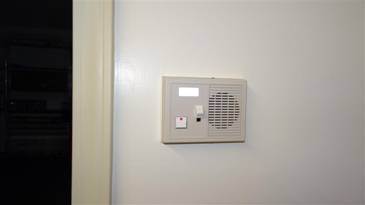
The idea here is to have a tasteful, office appropriate wall console on the Lab side which was functionally identical to the bold red Star Trek wall console on the Shop side. |
|
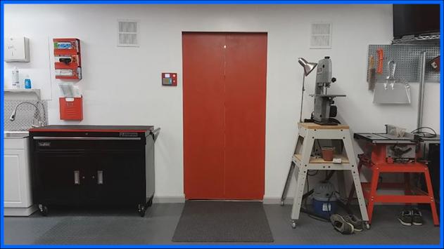
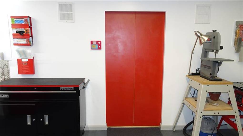
Here it is, all done (photo 2019-09-05), viewed from the Shop side. All the shop walls, in both the main section & the CNC shop are bright white with medium gray trim. Everything else is either black, gray, metal or the official accent color red. So, the doors in red are really right at home.
When the doors open, you walk through to the Lab and the doors close behind you. Suddenly you’re in a beige/woodtone office environment. The doors on that side are painted the light beige wall color. I love the Oz effect where now you’re in a whole other place.
The wall vents serve as access panels to the motor/gear assemblies. It also allows air pressure to equalize preventing the doors from rattling. |
|
Working on the electronics for the Lab side console. |
|
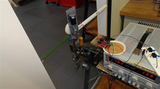
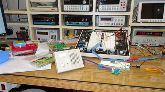
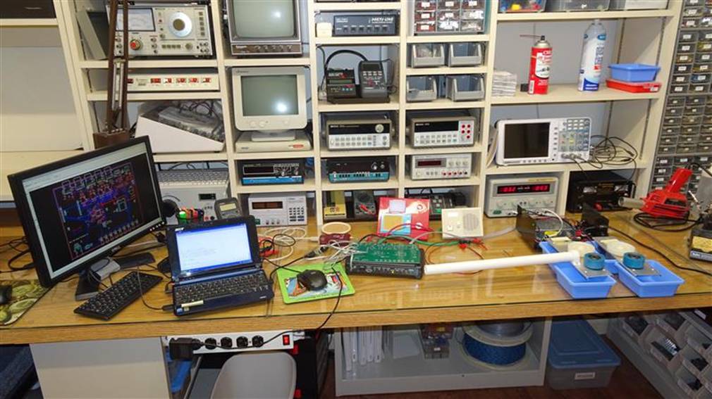
Having just assembled the Controller PCB, now I’m testing the motor control using the actual controller instead of my µC Development Bd that I was using to get the project started. Everything is together here, the Controller, both wall consoles, both motor/gear assemblies and the motor drivers.
Here is where I started writing the real software. Using DC Gear Reduction Motors instead of steppers meant that I had to control their speed using dual Pulse Width Modulators (PWM). This was necessary as I needed to control the ballistics of the motion so they would slow down at the end of travel and not bang. Not only that, but it turned out that the motors are faster in one direction than the other. My original goal was about 1 sec. of travel time, so I had to run the motors at 14.25V instead of their rated 12V. This is really no problem as there is no heating issue during the 1 second they are in operation.
I divided the travel time into 10msec steps. This granularity allowed me to tightly control the motion using the PWMs. I ended up having to treat each motor, in each direction, with a different set of PWM changes. I triggered the “swooosh” sound so it would start just a bit into motion for maximum effect.
On the console, on either side, there is a button and a red LED. When the LED is off, it is in Manual Mode. Just press the button to open or close the doors. If the LED is on, then it’s in Auto Mode. To switch between the modes, hold down the button for 2 seconds until the LED goes on or off indicating the new mode.
On the floor are contact mats. These are ignored in Manual Mode, but when in Auto, stepping on them on either side opens the doors. After you go through, you are on the mat on that side. 1.7sec after you step off, the door closes.
|
|
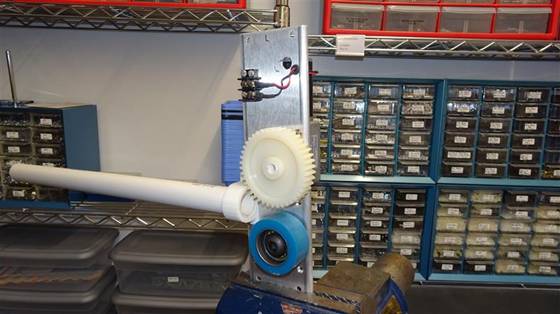
One side’s electromechanical assembly. The aluminum plate is holding the DC Gear Reduction Motor (on the back). It’s shaft protrudes to the front onto which I have a D to slotted shaft adapter that I 3D printed. This allows it to mate to the large nylon gear. The long tube is where the gear rack slides in and out as the door opens and closes. The green gear rack is not present in photo above, see it in the photo below in a rear view of the assembly where I am first testing it. |


|
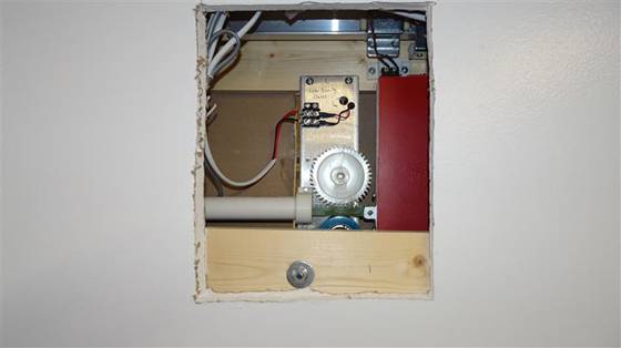
Above is one of the motor assemblies actually mounted in the wall. For the whole project, I constantly tried not to mess up the walls any more than necessary, after the ridiculous amount of work it took to build it in the first place. |
|
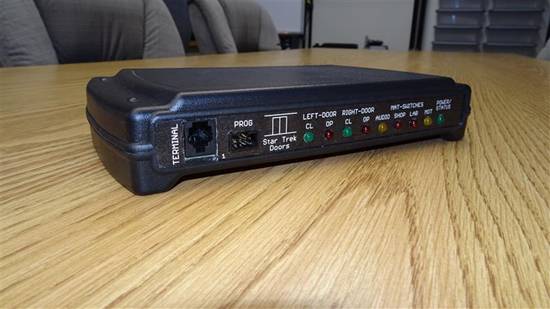
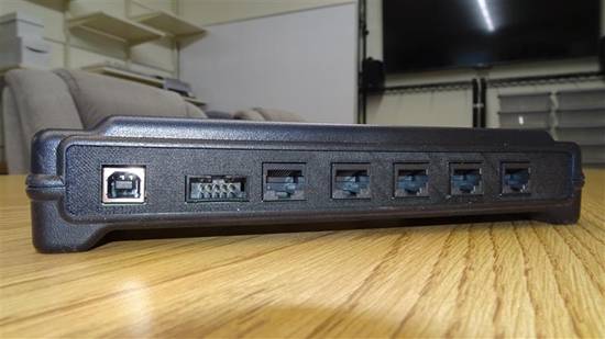
Controller Front Panel |
|
Controller Rear Panel |
|
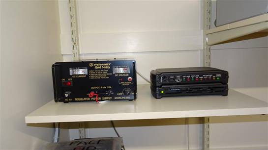
Power Supply & Controller unit with Motor Driver chassis under it, all in place on shelf next to doors. |