
|
Electronics & Maker Projects (page 13) |
|
Kitchen Cabinet Rack (CNC)
|
|
Basement Stairs Trim (3DP) |
|
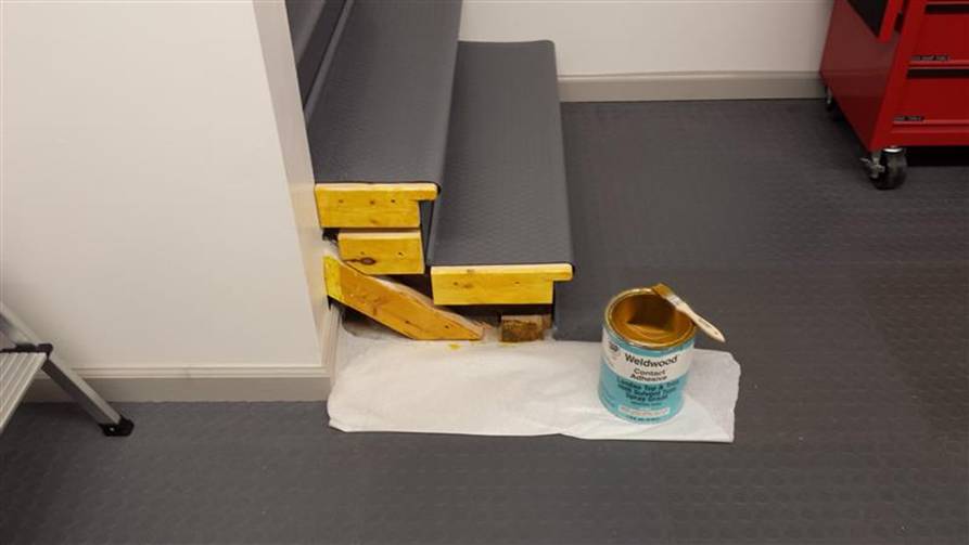
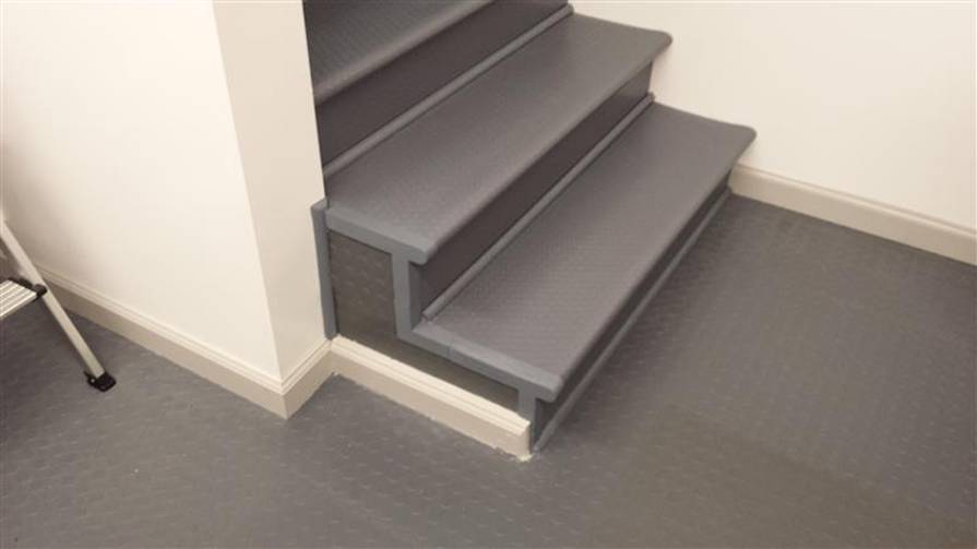
The basement stairs stayed the way the builder left them for many months. Just wood painted black, with the paint quickly wearing off. I recently covered them with gray coin pattern PVC mat, pretty much designed for use in garages. I bought the thinnest stuff I could find because I wanted it to wrap around the bull nose of the stairs.
At the bottom of the stairs the structure was showing with uneven protrusions. I built it out with 2x4s and cut some coin mat and glued it to the newly created side. I designed some trim pieces to go over the edges and bullnose and 3D printed them. Linda then painted the whole thing. The bottom photos show before and after. |
|
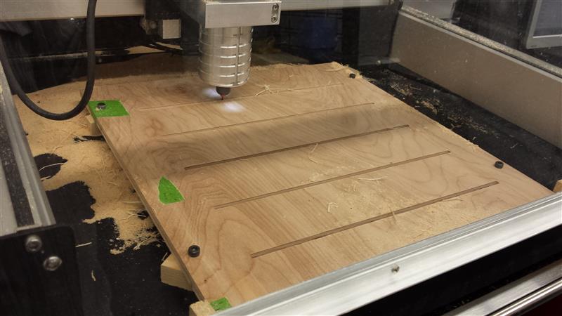
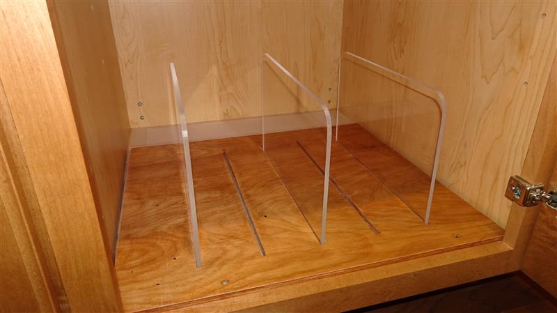
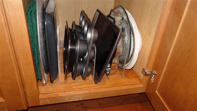
Linda wanted something that would divide pans and plates that were oriented vertically in a lower kitchen cabinet. I went through several ideas, but in the end wanted to go with something that wouldn’t look out of place and kind of disappeared.
I CNC’d 3 acrylic dividers, then CNC’d 5 channels into a wood base panel, all the way through. This way, she could arrange the dividers any way that worked. The tight channels keep the dividers upright. |
|
SwitchBot (Electronics, Software, 3DP, CNC, Linear Actuator, Servo)
|
|
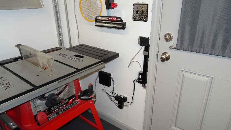
We replaced the light by the rear basement door with a floodlight fixture to better light up the back yard. I put in a photocell so it would turn itself on and off. However, the rear porch area is under the deck, leaving the photocell in the shade and making the floodlights stay on most of the time. Yes, I know I could have replaced the switch with a timer, but I would have had to get rid of my beloved diamond-plate switch plate that I brought from FL. The timers, due to their user interface, use a Decora type faceplate which is almost all opening and no plate.
I decided to make something which would normally be out of the way, and then at programmed times reach up and turn on or off the light switch then retreat. That way it wouldn’t ruin the view of my switch plate. When I explained my design goals, Jack of my breakfast group said “You had to do it!”. Exactly! |
|
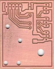
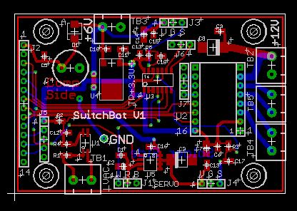
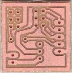
Small PCB I designed & CNC’d to break out the multi-conductor “tether” cable which feeds the servo, hall sensor and µswitch. |
|
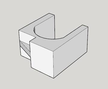
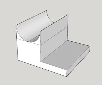
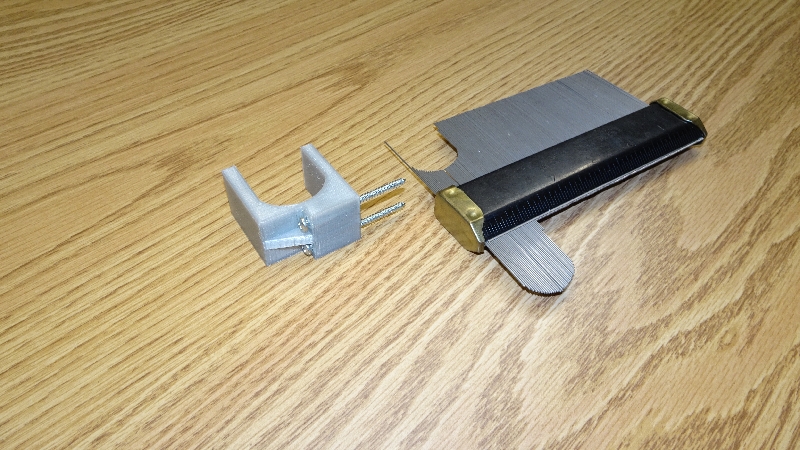
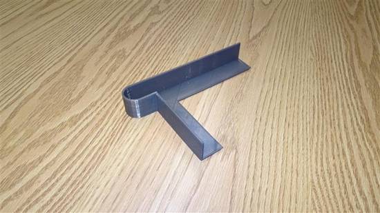
Captured the shape of the linear actuator’s body with the contour gauge, then designed & printed a bracket to hold it’s upper enclosure. |
|
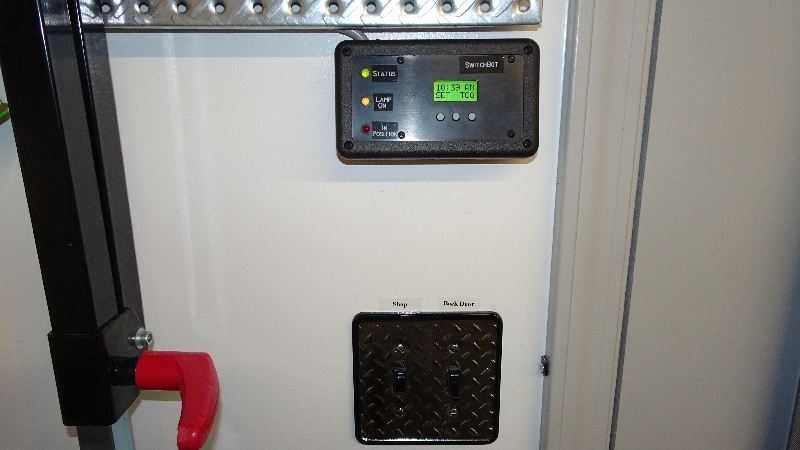
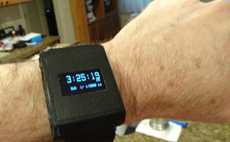
Above shows the user interface. The top line of the LCD shows the current time. The bottom line has SET over the left button and TOG over the right button. Pushing Set lets you either set the time or set the Toggle On & Toggle Off times. Pushing TOG makes the unit immediately toggle the switch to the opposite state that it is currently in, mainly for demonstration.
The top LED is Power/Status, the next one is yellow and shows you whether the floodlights are currently on. The bottom LED is red and illuminates whenever the linear actuator lifts the servo assembly to the level where it will stop to let the servo execute a toggle. That level is detected by the hall effect sensor seeing the magnet placed at just the right level on the door molding. |
|
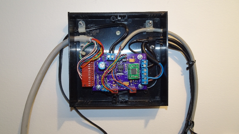
Interface (PCB layout above & finished unit below) designed for SwitchBot. The multi-conductor cable on the left goes up to the user interface. The one on the right goes up to the moving Servo/Hall-Sensor/µswitch assy. |
|
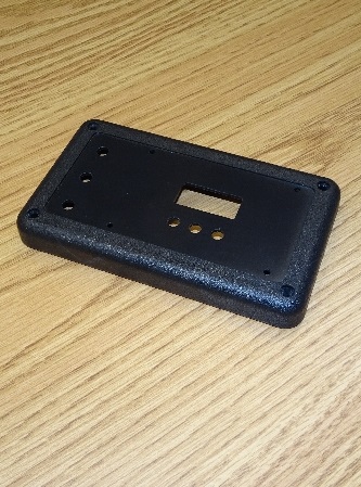
The User Interface uses a commercial electronics enclosure that I CNC’d to make the LCD opening and the pushbutton, LED & PCB mounting holes. |
|
One of the AC adapters puts out 8VAC. It’s just a transformer in a wall-wart, no rectifier or capacitor. I installed the new quad outlet with one socket fed from the load side of the light switch. With this setup, I have a low voltage AC signal presented to my Interface Bd where I detect it with an opto-coupler circuit which gives me a conditioned signal for the µC saying whether the floodlights are on or off.
That way, when SwitchBot is in the process of flipping the switch, it knows when the change (on-to-off or off-to-on) has actually happened and to stop vertical motion. It’s this feedback that really lets the whole thing work. Had I sprung for an extremely expensive linear actuator which has built-in positional feedback, I could have done without this, the hall sensor and the µswitch. |
|
WristClock (Electronics, Software, 3DP, CNC)
|
|
When the band broke on my latest Casio watch, I just went without and started looking at my cellphone for the time. Rather than shell out $10 for a new band or $11 for a new watch, I thought it would be better to do a month long multi-faceted development project.
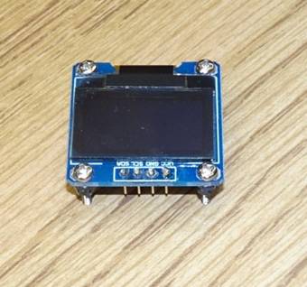
Well, actually a while back I had ordered on a whim a couple OLED displays. They have a .96” diagonal display area with 128x64 pixels. There’s a matrix of anode and cathode junctions which put a small current through electroluminescent material which emits light at that point. Therefore, unlike an LCD which blocks light and needs a backlight to be seen under low light conditions, the OLED actually emits light. These units have an “I2C” interface which allows control with just two µC I/Os. The same I2C bus also talks to the RTC (Real Time Clock) chip. It seemed perfect for a watch project.
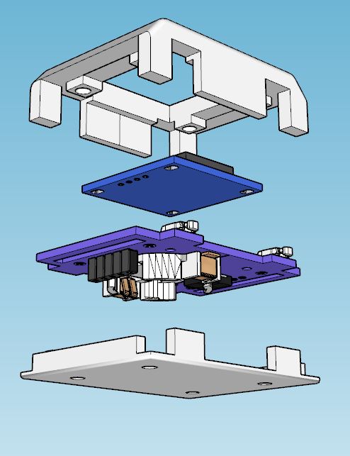
Digital watches use dedicated watch ICs with the chip bonded directly to a tiny PCB. Since I was going to use conventional surface mount parts with a general purpose processor, I knew it would get fairly large. Hence the name “WristClock”. Coincidentally, people are now wearing smart watches which are pretty large, so maybe it won’t look that out of place.
In trying to keep things small, I used a member of my 9S08 µC family that comes in the smallest package I’ve ever worked with. It has 25mil (.025”) lead spacing and was indeed quite a challenge to solder, even under the microscope. I used the smallest packages I could for all the parts and used every facility of the µC such as internal pullup resistors and internal clock generator to minimize the number of passive components. I used a 6KHz piezo for a “beeper” because it was much smaller than the 4KHz I would normally use.
Even given dimensional drawings it was hard to get a feel for size when looking for tiny surface mount pushbuttons. I wanted to minimize board space but also have the actual button large enough to easily actuate. I had very little to choose from in stock, most of my switches were thru-hole, so I had to order several switches to evaluate.
|
|
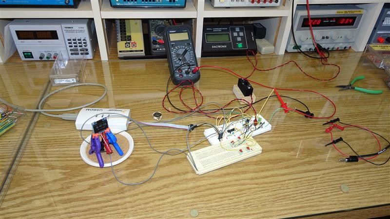
Development work on WristClock was done using a DIP version of the µC. This allowed using protoboards. All the software was done and tested before laying out the PCB. |
|
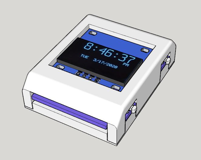
There are 4 pushbuttons, with the upper left button used to powerup the unit. If you just push and release, the display stays on for 2.5sec. If you hold it down, it will turn off 2.5sec after you release it. This button also allows you to exit from any of the sub-functions. The button on the lower left is “Select”. The upper button on the right is “Up” and the lower button is “Down”.
One thing I never liked about the watches I’ve owned is how hard it is to set them. On WristClock, I made it where you just hold down “Select” for .5sec, then you’re given a choice to set the Time or Date. If you select Time, the display shows the most recent time digits, full size, with an easy to see cursor under hours tens. You increment or decrement each digit, pushing Select to advance to the next one. It works the same for Date. This makes setting the Time & Date easy.
I also have it do a quick battery threshold test on powerup, and when it starts to get too low it puts “Lo” at the end of the date line.
|
|
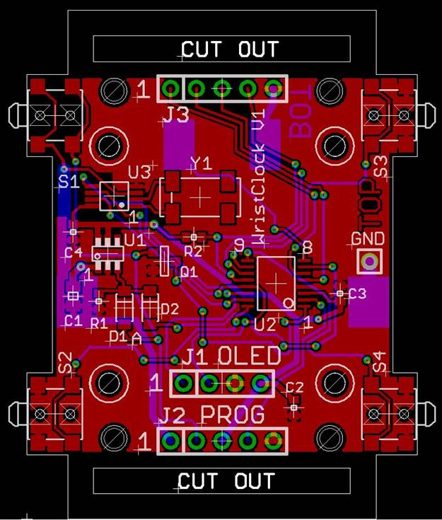
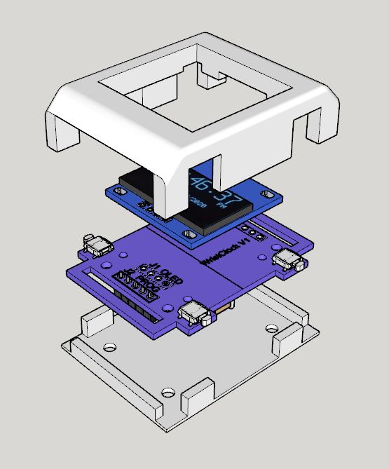
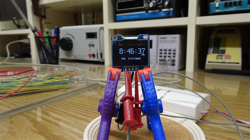
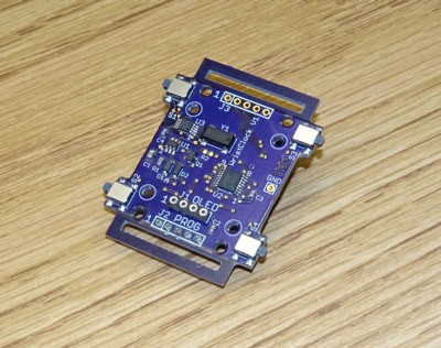
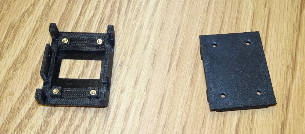
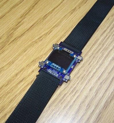
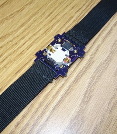
I put two slots in the PCB to attach a wristband. I knew I would be 3D printing the enclosure, but something this small would not be that strong. That’s why I had the PCB provide the physical strength necessary for the wristband. There were so many details to consider in wrapping an enclosure around the electronics that I had to recreate the PCB in 3D CAD along with the OLED board. Only by starting with those could I design an enclosure that took into account their shapes without having to make it larger than necessary. When I was done, Linda took some strap material from a camera case, put it through the PCB cutouts and sewed tight loops top and bottom. Then she sewed in velcro, making it relatively easy to take on and off. I don’t know how much I’ll actually wear it, but it was a great project. |
|
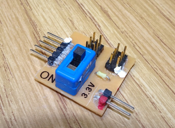
A subproject became obvious early on. There was no way the normal 6-pin dual row .1” spaced male header µC programmer connector was going to fit on this project. I had to trim it down to the least signals necessary and put them on a much lower profile connector.
This meant I had to make an adapter that mates with the µC programmer pod’s 6-way female connector and breaks it out to a simple header that I could make a cable to take the signals to the WristClock Bd. Since this was a simple PCB, I decided to make it on the CNC. I used thru-hole parts and laid out a single sided PCB with the traces on the back. |
|
Heat Gun Hanger (3DP)
|
|
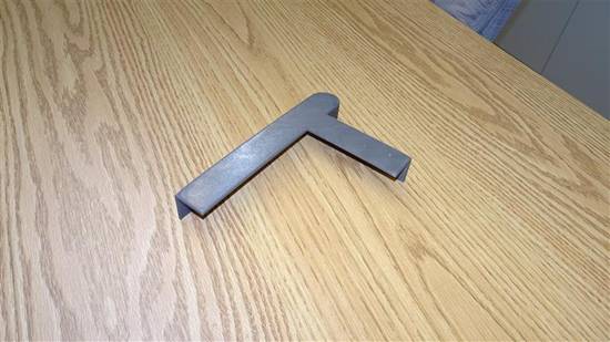
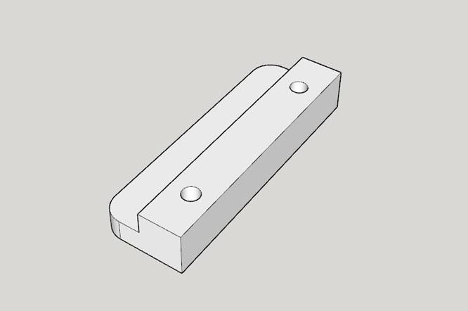
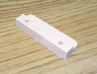
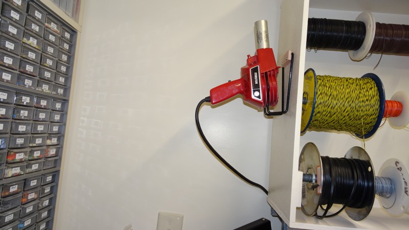
The corner of my hardware bench where I keep my various soldering irons has always been crowded. Recently I thought how nice it would be to get the heat gun out of the way and hang it on the side of the wire rack. You’d think I could just use some hooks or something that already exists, but I ended up spending more time going through my storage boxes looking for the right shape than it took to make the perfect thing.
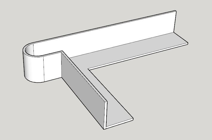
I made a hanger with a lip that lets the heat gun’s stand rest perfectly in the resultant slot. |
|
Bluetooth Receiver Enclosure (3DP)
|
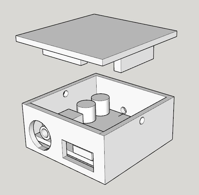
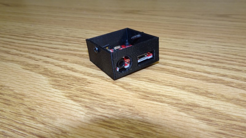

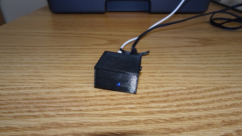
|
I’ve had this little Bluetooth receiver board sitting around for a long time. I finally hooked it up to the stereo and it sounded pretty decent. I designed a little enclosure for it with openings for the stereo mini phone and µUSB power connectors. I also put in a tiny hole for the blue LED indicator. While not audiophile quality, it does let me send any track I want from the network drive to the stereo via my phone without buying a new stereo. |