
|
Electronics & Maker Projects (page 14) |
|
Netclock Bi-Matrix LED Clock (Electronics, Software, 3DP, CNC)
|
|
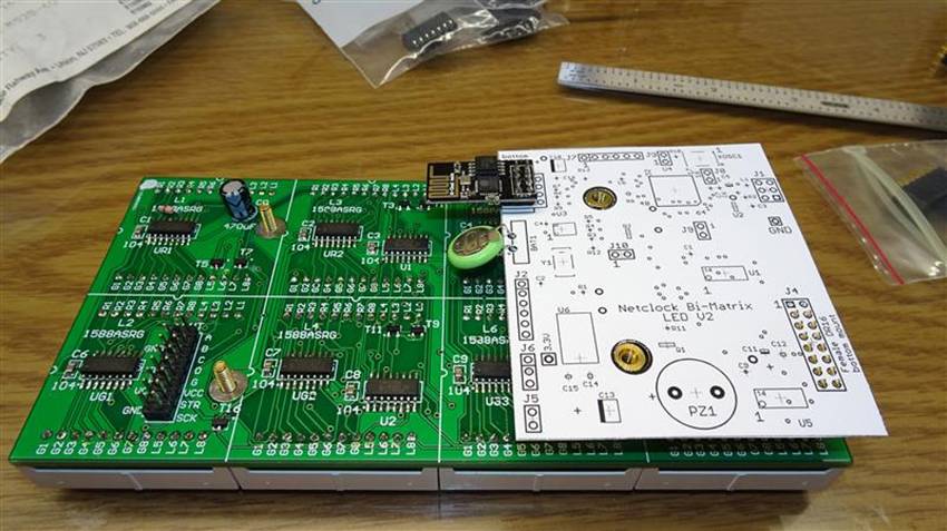
I had purchased this LED Matrix kit some time ago from China as it was really cheap. It came with eight 8x8 dot LED blocks, a PCB, some shift registers and two 3 to 8 line decoders. The dots actually have 2 LEDs each, one red and one green. I’ve made several LED dot matrix clocks over the years, but always using just red LEDs. The whole “kit” was about $9. To layout a PCB, have it made then buy parts at say DigiKey to make the exact same thing would cost well over $100.
What I didn’t realize when I ordered this kit was how basic it actually is. Each color has a 32 bit shift register to drive the columns. There’s a 4 to 16 line decoder, made from two 3 to 8 line decoders, that drive the rows. That means you have to do all the multiplexing yourself. While all my previous LED matrix projects did indeed rely on software multiplexing, I had just assumed that any design today would use I2C or SPI LED matrix driver chips. But no.
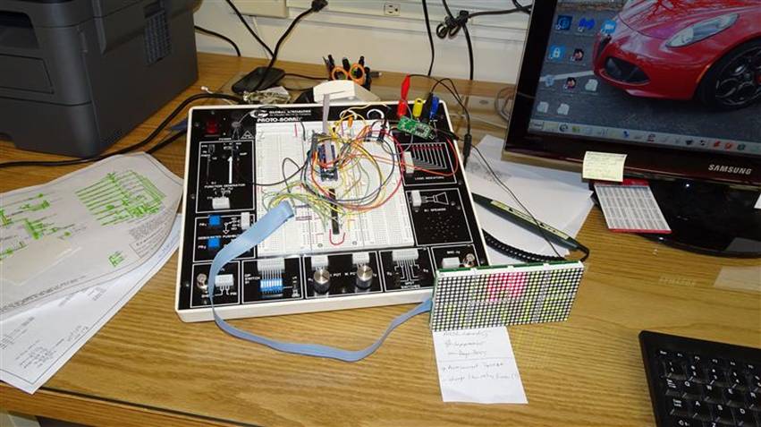
First I built up the matrix “kit”. Then I went about putting together a circuit on my prototyping station using my own 9S08QE128 breakout board. The first goal was to just light up all the LEDs. Well, no wonder this thing was so cheap. One of the matrix blocks was WAY brighter than the rest. I was used to LEDs being graded for brightness so they could be matched up, but this is China! Naturally, I had soldered them all in and I didn’t have anything to replace the overly bright block with anyway. I just put the whole thing back on the shelf where it sat for a few more months while I did other projects.
When I ran out of ideas for projects, my mind wandered back to the LED matrix. You know, I said to myself, having to do the multiplexing in software was annoying, but it could give me the flexibility to do something about that outlier LED block. What if instead of multiplexing at 60Hz, I did it at 120Hz and for every-other refresh I blanked the dots/pixels in that block? With a little software gymnastics I gave it a try. It really knocked down the overly bright block and I decided it was good enough for my project.
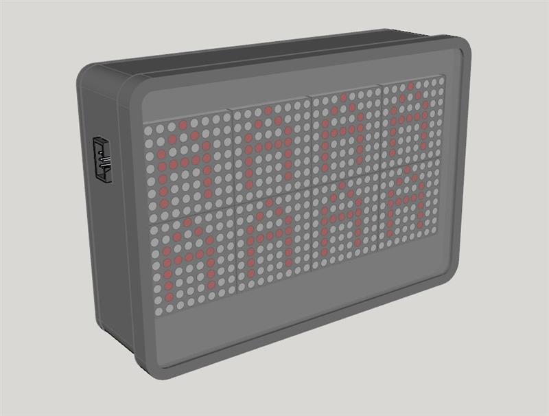
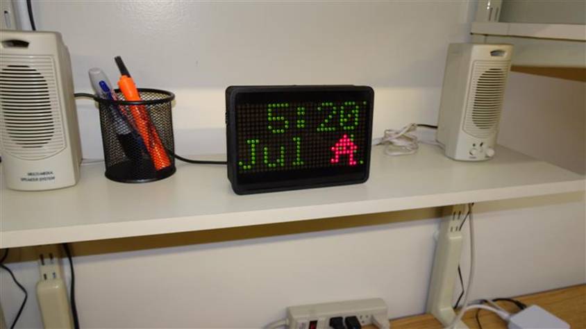
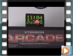
I always like to visualize what I want the final product to look like before I get in too deeply. The 32x16 dot matrix lends itself to having the Hours & Minutes on the top and the Month & Day on the bottom. I had always pictured putting this in our “diner” area as the only clock up there is a chrome analog clock with a neon surround. It’s really just a display piece and the clock stops when I turn off all the decorations, so it doesn’t really keep time.
Now that our “diner” has the arcade game that I put together, where you can play my 80’s video game Alien Sidestep, I thought it would be great to follow that theme. I’ll have the time & date in green, and every so often have one of my aliens from the game go across in red. It should look great mounted above the arcade game.
Before laying out a PCB, I decided to take my proto board mockup to the point where all the software was done. That way I wouldn’t miss any hardware I might need to make it all happen. I put a surface mount RTC (Real Time Clock) chip on an adapter bd to allow plugging it onto the proto station. I wired in a WiFi module, so like my other net-clocks it will go out on the web every day to set itself to the exact time.
I also wired in a µwave motion detector. The clock, mainly due to the LED matrix, draws almost half an amp! No reason to have it on when no one is around, drawing that kind of power and generating heat. With motion detection, it will see if anyone is in the diner. My software will have it come on for 10min, with the timer reset every time motion is detected. I more typically use a PIR motion detector, but I wanted the enclosure to have a nice clean look, without the big “eyeball” Fresnel lens.
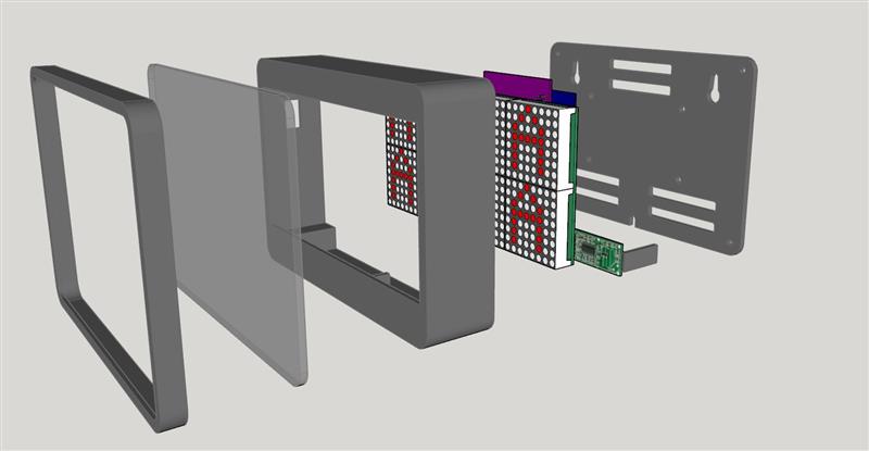
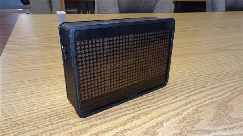
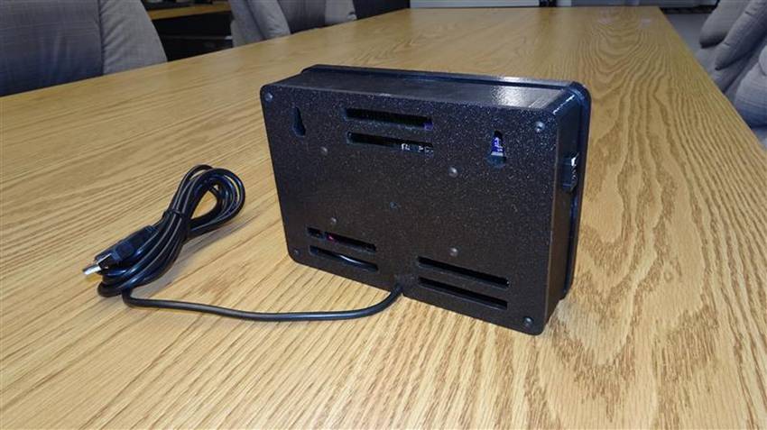
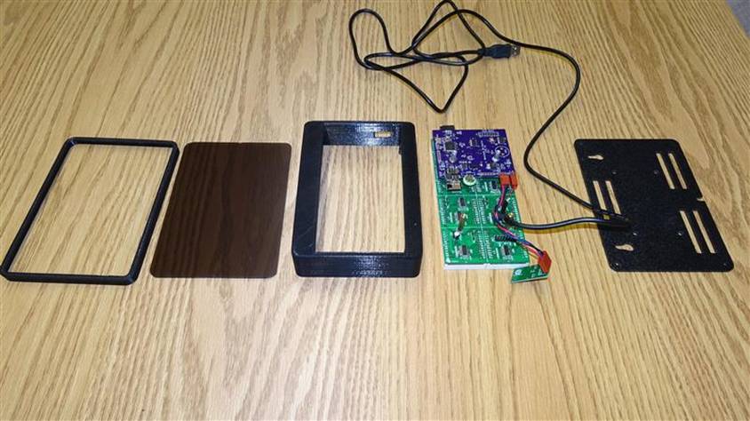
This was a great project in that it required work in a lot of areas. Naturally I had to design the electronics and write the software. When that was done, I laid out a PCB that would plug onto the back of the LED matrix bd. I designed and 3D printed the enclosure’s main body & front bezel surround. I milled the front gray plexiglass filter and ABS rear panel on the CNC. See the CAD drawings of the whole project exploded and the photos showing the final pieces.
Check out the video of the clock mounted on the arcade game actually working. The red dots/pixels look much nicer in person.
|
|
BulbBot (Motor, Servo, Electronics, Software, 3DP, CNC)
|
|
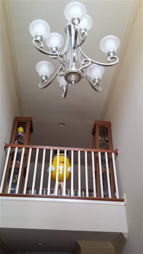
In our entry way we have a chandelier that is so high up, I would never climb a ladder that high, even if we had one. Not only that, but the bulbs are in decorative glass “cups” (for lack of a better word). The trouble is, the cups & light bulbs face UP!
If your bulbs face down, there are many bulb changers available which are just long poles with some type of bands which grip the bulb. You just shove it around the bulb and twist. But when the bulbs face up, it’s a whole other problem. The only choice is to construct a grip-and-rotate machine using a linear servo, slip ring and lo RPM gear motor.
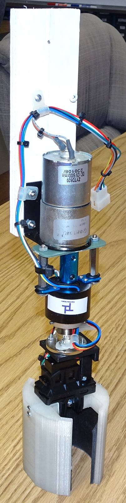
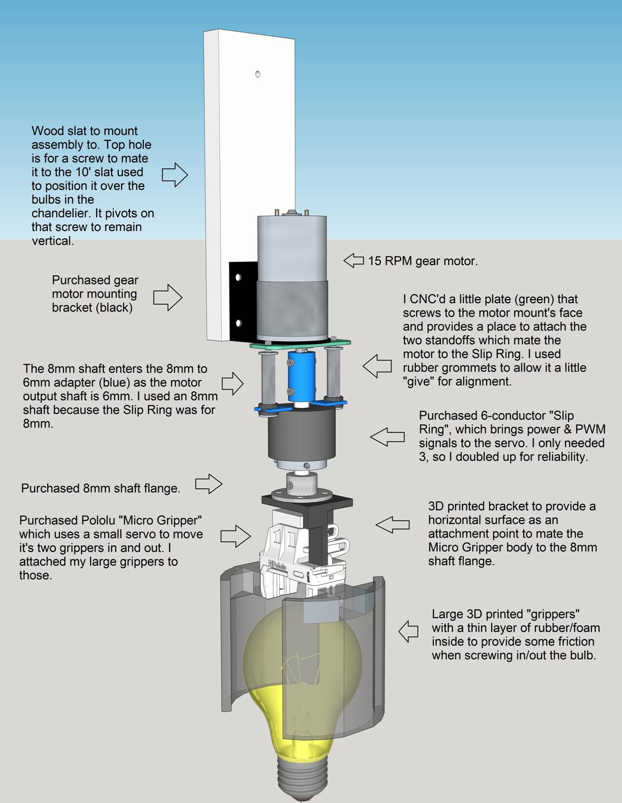
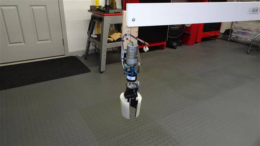
I started with a Pololu “Micro Gripper” which I had purchased on a whim but never used. It has a small servo motor which drives a gear that creates linear motion for two small “grippers”. I designed and 3D printed grippers big enough to grasp a standard light bulb, then attached these to the existing small grippers. They had to be proportioned just right, as the inside had to open wide enough to allow lowering it onto the light bulb, and the outside couldn’t be too big as it had to fit inside the decorative “cups”. I put some thin rubber material on the inside to create friction so hopefully it will twist the bulb rather than just rotate around it.
The Micro Gripper attachment points were really meant for some kind of clevis, so I had to design/print a custom bracket which would use these holes to create a horizontal surface on top of the servo. That’s where I needed to put an 8mm shaft flange who’s axis would be in line with the center of the bulb rotation. From there, an 8mm shaft is attached which goes through the Slip Ring and up into an 8mm to 6mm shaft adapter. I chose an 8mm shaft because the only reasonably priced “through” slip ring I could find was made for an 8mm shaft. It has set screws to secure the rotating end to the shaft.
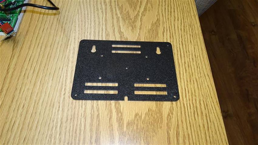
At the top, the other side of the 8mm to 6mm adapter attaches to the 15RPM 12V gear motor. I also purchased the gear motor’s right angle mounting bracket. I CNC’d a little plate which along with the mounting bracket screws to the motor. The plate provides two holes where I have long standoffs that mate the motor with the slip ring housing. The standoffs rest on two rubber grommets where they screw to the slip ring’s mounting flanges to provide a little flexibility in case of minor misalignment. I created a wiring harnesses for the servo-to-slip ring side and for the slip ring & gearmotor side. This put a 6-way .062” molex connector at the top of the assembly, ready to mate with the long multi-conductor cable which will run the length of the pole to the controller box.
|
|
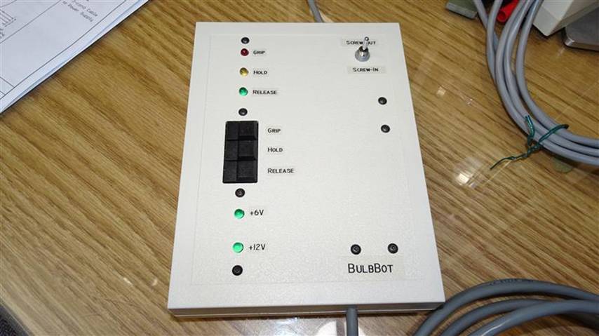
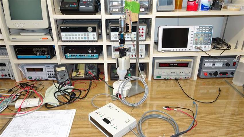
With the electro-mechanical aspects assembled, it was time to build a controller. This wasn’t overly complicated. All the gear motor needed was a 2-pole 3-way center off spring loaded toggle switch. That way I could have it rotate one way or the other for screwing-out or screwing-in the light bulb.
The servo on the gripper would need the standard PWM positioning signal. At first I was going to make that variable. But, picturing the actual operation, me standing there on the catwalk holding this 10ft long wood slat, teetering on the hand rail with a weight for counter balance, it sounds like I will be busy. So, I decided to have just 3 distinct gripper positions. “Grip” will be the strongest, meant to hold the bulb while it is rotating to screw the bulb in or out. “Hold” will be just strong enough to hold the bulb while it is being moved with the long slat to and from the chandelier. “Release” will position the grippers enough apart to place them over the bulb in the chandelier or to remove it once retrieved.
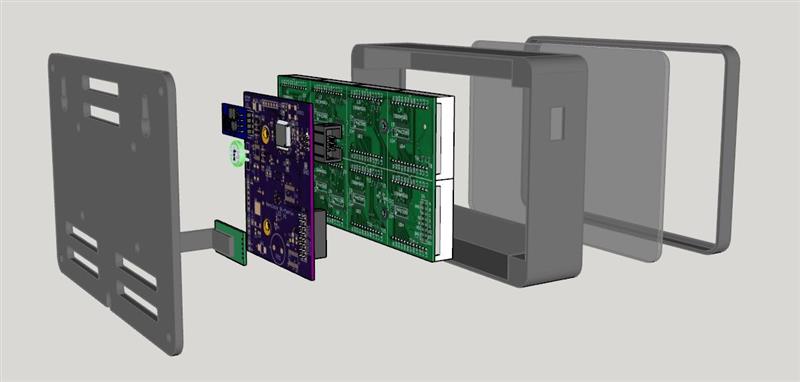
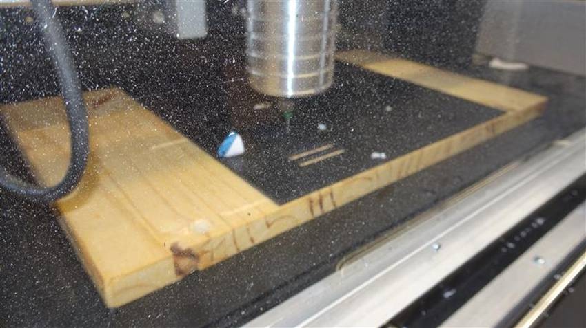
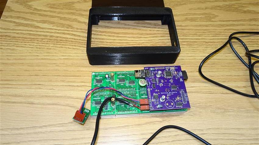
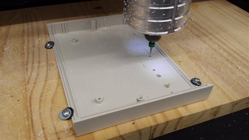
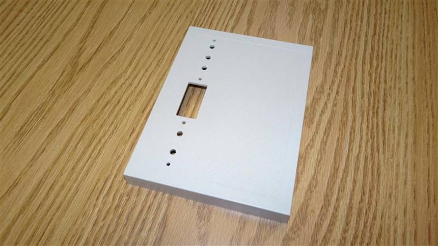
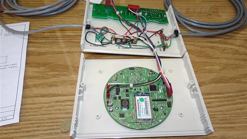
There will be just 3 buttons to put it in those states, with an LED indicator to show what state it’s currently in. Since I’ve already spent some money on the gripper, slip ring and motor, I decided to use a couple old PCBs left over from my career work for the electronics. I had an old board with 3 buttons and 5 LED indicators, perfect for the user interface. So I milled a Simco enclosure from my stock to provide openings for the buttons, LEDs and screws. Again, like in a some other recent projects, this makes the whole CNC setup worthwhile. I always wished I could modify off-the-shelf electronic enclosures, no matter what shape opening I needed. For decades I did this with hand tools and never could achieve that nice clean factory look.
Since I have to generate the PWM signal, look at the buttons and illuminate the LEDs, I obviously needed a µC. Again, I used an old PCB with my favorite 9S08QE128. It’s the round PCB in the photos. Important to use this chip as I already have lots of PWM routines written and ready to go.
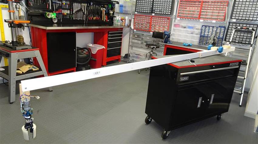
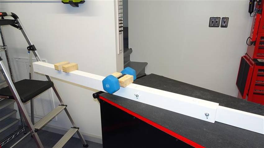
I wrote the software and finished the wiring. I then constructed the long 10’ wood slat that will be the arm that gets manipulated from the catwalk over the entryway. It will rest on the catwalk’s hand rail, and be somewhat counter balanced by putting a small hand weight (dumbbell) on the catwalk side. I’ll have to hold this assembly, position it over the target chandelier bulb, lower the grips over it and push the “Grip” button. Then, push the toggle switch in the “Screw-Out” direction. When it’s free, pull the whole thing back to the catwalk then do the reverse to install the new bulb. Really!?!
Though the project is pretty much done, I have a problem that I don’t normally encounter. As I write this (2020-09-16) none of the bulbs in the chandelier have ever gone out. I don’t want to just try it in case I get the bulb out but can’t get a new one in. That would cause the problem I’m trying to prepare for. It might be fine for years as far as I know. So, at this point, I’m going to leave it right there. When that first bulb goes out, I’ll put the whole thing together and see if it works. |
|
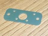
CNC’d Mounting Plate |
|
CNCing Controller Enclosure |
|
Controller Electronics |