|
Electronics & Maker Projects (page 18) |
|
[2022-03-24] Back in Feb of 2021 I finished a big project, “The Prisoner Game” (story on “Electronics & Maker Projects pg15”). It was a vertical electromechanical game, but even though it used a chrome ball, you really wouldn’t call it a pinball machine. More of a balancing skill game. It was such a huge job, that for months after that I limited myself to smaller projects.
In late Sept (2021), I missed the challenge of a big multi-faceted project and once again found myself web surfing for “vertical pinball machines”. This time, I hit something I’d never seen before. In 1984, Williams created a prototype game “Still Crazy” which truly was a vertical pinball machine. They never went into production, and only 3 are known to exist. I found pictures and videos online and studied them intensely trying to decide if I could use this concept.
A Straight Up Challenge
A normal pinball machine has a small incline for the ball to roll down, hitting various obstacles and reaching the flippers at the bottom. To create a vertical pinball machine, something had to keep the balls from just dropping at full speed. Here they cleverly used a series of “ball guides” which are kind of maze walls. In 4 distinct sections, these somewhat horizontal walls become a kind of track that the ball goes back and forth on as it makes it’s now tempered overall descent.
The graphics for “Still Crazy” were applied not only to the playfield, but also covered a lot of the front glass. It was impossible to get a feel for how the machine was made through all the graphics. Fortunately, someone had taken fairly good photos of the game with the glass removed.
I had reached a decision point, whether to pursue this concept or move on. Just like “The Prisoner Game”, the tipping point was when I thought of a theme. I always loved “The Outer Limits” TV show from 1963-65. The control voice opening and music alone told me this would be a great concept. That’s when I decided to actually build it, knowing it would consume many months of my life. Maybe I'm "Still Crazy" ?
Sherlock Ohms
After much detective work, I found little hints here and there in descriptions of the game, sometimes just photo captions, and put together some useful numbers. The game used a 3/4” ball (“The Prisoner Game” used a 5/8” ball and a typical pinball machine uses a 1 1/16” ball). Also, I found the rough dimensions of the game. I ordered the most generic Williams flipper bats that matched the photos. Having them in hand allowed me to take exact measurements.
I used the best glass-off photo I could find, cropped it and tried to adjust for angle to get a flat playfield view. Then, using all the dimensions for the game, flipper bat, ball, etc., I started counting pixels. I developed a ratio of how many pixels per inch the photo represented which allowed me to count pixels and get any dimension I needed. With the understanding that this was developed in the US in 1984, and that you could consider the playfield starting point as a woodworking project, I deduced that wherever possible they would use inch and fractions of an inch spacing. That let me round all the calculated numbers to the nearest fraction of an inch.
I made the doctored photo it’s own layer in Sketchup, then created a vector drawing of the ball guides over it. This all came together and I was able to make what I think is a pretty accurate drawing of the playfield with its ball guides. Over time I would adjust, modify and add more pieces to the layout to suit my game.
The reason I went to all this trouble instead of just starting from scratch is that even more so than in a pinball machine, there must have been an enormous amount of trial and error put into the playfield’s development. The timing of the ball delivery to the first flipper vs. the likely position of other balls in the maze, alone, is carefully crafted to enhance game play.
There are 4 flippers that drive the ball up 4 curved “ramps” to deliver the ball to the next level (and acquire points). But just like pinball, unless you hit the ball just right with the flipper, your ball may go in any direction. Whoever did the layout at Williams for this game’s ball guides successfully mimicked that. If you flipper a ball up a ramp, but it bounces back, there are protrusions that can intercept it and send it through parts of the same level again. The game ends up having the same wild anything-can-happen excitement of a horizontal pinball machine. Given the 4 flippers and 5 active balls (5 is my choice after experimenting), it can get pretty crazy.
The Game Will Soon Begin
To nail down the difficult elements, I started by using scrap plywood to prototype the bottom 25% of the game board which has the ball delivery “wheel” and the return “drain” holes. I learned a lot of details about pinball machines during development, including some of the terms. The “drain” is the area below the flippers, where your ball is lost. For my game, there is a hole on either side where balls that get past any of the 4 flippers get channeled to via "outlanes". The balls go through the holes and roll on internal angled channels ("subways") that take them back to the bottom of the “wheel”. The wheel picks them up and drops them off on a ramp which delivers them to the 1st flipper.
One thing I couldn't find online is the angle of the playfield. I even left questions on forums where there was discussion of "Still Crazy". I got a few responses, but the numbers were just people guessing and seemed way off. Experimenting, I ended up giving it the same 15° angle as my Prisoner Game.
Back to my lower 25% prototype, which I now propped up at 15°. The internal channel needed to be a kind of Z profile. It needs to let the ball roll but keep it at an angle that would force it to fall through the hole at the bottom of the wheel back onto the playfield surface. I had 3D modeled the lower area, and it became apparent that no aluminum extrusion was going to give me the crazy angle that I needed.
So, I had to make the channel with my 3D printer. Due to the capabilities of my printer, I made it in 6" sections and put them end to end. I CNC'd the wheel from 1/16" Garolite (McMaster Carr), which is similar to phenolic. I designed and 3D printed the wheel's "rotator" which picks up, elevates and lands the ball on the lowest ball guide which delivers it to the first flipper.
I went on to 3D model the whole game a section at a time. Sadly the playfield was too large to fit into my CNC, although I used it for lots of other things in the project. Fortunately, there are only 4 large holes which I was able to make with a step drill.
The hole where the ball is delivered back onto the playfield at the wheel pickup point had to be drilled at a specific angle. Otherwise, the ball would not overcome the 15° playfield board angle to get back to the play surface. I bought an interesting tool called the Milescraft 1318 DrillMate Portable Drill Guide. It allows your handheld drill to act like a drill press, and is particularly good at helping you drill at specific angles. This is something my CNC couldn't do even if the board would fit, and indeed with good clamping it worked out great.
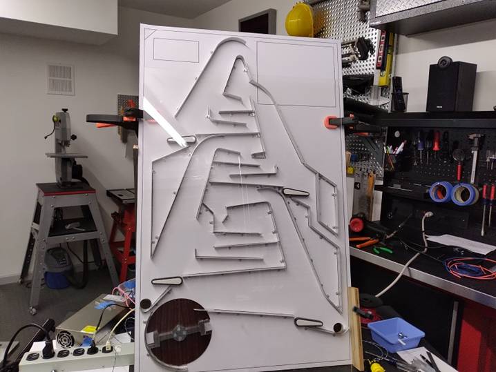
I completed my CAD design of the playfield which shows all the holes and all the ball guides. I converted it to a hires B&W line drawing and had it printed full size at Office Depot. After gluing it to the full sized playfield board, I started the process of creating the ball guides in all the shapes I needed.
Rather than bend flat strips of metal and come up with some small angle brackets to hold them to the playfield board, I decided to use aluminum angle extrusion, with one side 1/2" and the other 3/4". I used my sheet metal punch to punch out all the metal on the 1/2" side leaving only the little "feet" to mount it to the board. Once that was done, I would use my vise and assorted other tools and shapes to create the huge range of straight and curved ball guides. If you look at the photos, you can see why this process took quite a long time.
Flipping Out
When I had the basics of the playfield constructed, I researched and bought 4 Williams replacement flipper mechanisms. I was worried that having to flip the ball almost straight up might be difficult for the flippers, so I bought the strongest one of the standard units. Well, it never came together in my thoughts that yes, they had to go almost straight up, but far more importantly the balls are only 3/4" diameter, not 1 1/16". Those are about 2.8 times the volume and therefore the weight. I ordered a 48V supply, cranked it up to 50V which is the traditional flipper supply voltage, and BANG! The ball hit the aluminum, bounced off and flew across the room. I experimented with various voltages and finally settled on a more civilized 36V supply.
We Control The Electronics
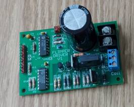
I slowly got the game basics together, and used a simple breadboard circuit to get things operational. After gaining a little experience, I began to design the first step in the electronics, the Flipper Driver board. The flippers would need 36V at about 10A each for a very short time. I had to take into account that each of the 2 player buttons fire 2 flippers at the same time.
Once a flipper actuates, it also closes a leaf switch. On older games it directly switched power from the Power Coil to the Hold Coil. The Power Coil actually bats the ball with tremendous force, then the Hold Coil takes over and is just strong enough to hold the flipper bat in position. The old games would arc and spark due to all the current it had to switch, but new ones just use the switch as feedback to electronically switch the drive from the Power Coil to the Hold Coil. This is exactly what I did. In my Flipper Driver Bd design, I put in logic to do the coil switching. In addition the signal from the player's buttons could be gated so ultimately the µC (microcomputer) would be able to disable the flippers when the game is not in progress.
Instead of making one board with 4 flipper drivers on it, I decided to make a smaller board so I could locate each one right by it's flipper mechanism. The board has logic, large power transistors and a huge capacitor. The capacitor handles local storage of energy to reinforce that very short hi-current blast that the Power Coil needs.
Ball Detection
I experimented with 3D printing little gates which used tiny bearings which would swing when the balls went through. On the back of the playfield on the same shaft I had a little arm with a magnet at the end. It would swing through an arc where the magnet would trigger a precisely placed Hall Effect Sensor. These detect a magnetic field and I often use them as position sensors. It worked, but the mechanical violence of the game was just too much for the assembly, so I decided to go non-contact.
I had a bunch of tiny IR (infrared) obstacle detector PCBs that I had bought cheap on a whim from China years ago. It has an IR LED (emitter) and next to it an IR phototransistor (detector), both facing the same direction looking for reflection. They're meant to be used on robots to detect walls, etc. I removed the emitter and detector, faced them at each other across a gap that the balls would traverse, and used the opposite logic to detect when the beam was blocked.
It worked pretty well, but the emitter's beam was so wide I thought it might sneak around the ball and not provide a clean break. I looked through lots of data sheets, and eventually bought very narrow beam angle IR LEDs
I designed and 3D printed little upright housings for the emitters and detectors. Then I designed tiny PCBs to solder them to which I CNC'd and mounted on the back of the housings. Of course there's no way to aim invisible light. So, I used a small cheap black & white security camera that I keep around for just such an occasion to aim the emitter's beam exactly at the center of the detectors. It all worked out great and there's no moving parts.
All My Circuits
The Flipper Driver Bd was just the first of many I designed for the game.
I had early on decided that the Outer Limits Game graphics would be all black & white or grayscale like the show. So, when contemplating the scoreboard, I wanted to use a white display, not the much more common red, green or full color. I also wanted it to look as sci-fi as possible. Poking around I found on Aliexpress some white emitting square-pixel LED matrix modules. There was very little data, but I took a chance and ordered some.
They took forever to get here, but when I lit one up on the bench with some jumper wires, I was thrilled with the look. They were simple LED matrixes with no electronics and I had to experimentally figure out the pinout since they had no documentation. With that, I designed a board that would drive 4 of the 8x8 pixel modules for a total width of 32 pixels. I would use 2 of these stacked for an overall 32 x 16 pixel scoreboard. I used driver chips that accept SPI serial data, which can be sent very fast from my µC.
I knew I wanted the game to feel as much like a pinball machine as possible. To that end, I decided to use "playfield inserts". These are the rear illuminated symbols that are flush on the playfield. Initially they were round and often had points values on them. This is what I wanted to use, but one problem was that, again, the playfield board doesn’t fit into my CNC. That meant I couldn't use off the shelf inserts because there was no easy way to make the exact size holes to match the standard size inserts.
My step drill had done a great job so far, so I decided instead to design the inserts to match the holes and make them on the 3D printer. I used a heated glass print bed to give me a perfect glass-like finish that I could apply waterslide points decals to. I used white PLA plastic and made the surface as thin as possible to let the most light through. Given there was still attenuation, I used very bright surface mount LEDs meant for illumination rather than indicators and drove them with 60mA.
First I designed a prototype PCB that I could make on my CNC. It included a transistor to drive the LED, and 2 holes so it could simply screw to the back of the playfield. This worked great, but since I would need 16 of these I did a formal layout and sent the files off to China. I specified an unusual white soldermask to have all the light reflect outwards. Eventually I printed out points values on clear water-slide decal sheets, applied them to the insert’s faces and Linda clear coated them.
Along with the 16 playfield inserts, there were 5 "risers" that were to be backlit. What I call "risers" are 3D printed panels that I designed specifically to drop into the areas that are surrounded by ball guides. Again I used a glass bed to make the surface smooth and used white plastic. I found on the web an artist that had done line drawings of the Outer Limits monsters. I grabbed these and manipulated them a little, then printed them out on clear waterslide decal material. I used LED strips to backlight them.
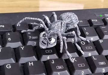
One more item to be illuminated was a "real" Zanti! OK, if you haven't seen the show in a while, there was one episode called "The Zanti Misfits". Look around the web and you'll see it's usually peoples favorite episode. The Zantis were aliens with large ant bodies with human (kind of beatnik) faces! What really made it memorable is they actually used stop motion to realistically animate the Zantis. Most of the Outer Limits monsters were just costumes, but here they spent the money and did the time consuming work of stop motion.
In researching all things Outer Limits when planning my game, I ran across a guy (Stexe) on Etsy selling Zanti replica refrigerator magnets. He does serious injection molding. I messaged him to ask if he would make a special one in grayscale, mentioning I was making a pinball game. I'm glad I did.
He does them in batches and wouldn't normally want to do a special one, but he was a big pinball fan and told me to get in touch with him after Christmas. I thanked him and put it on the back burner. Well at Christmas Linda surprised me with a grayscale Zanti! She had contacted him and he was moving to a new batch sooner than he thought and went ahead and made it.
I wanted to have bright LEDs light up the Zanti's face, so I designed a simple LED board including transistor drive and CNC'd it.
Actually I wanted to have all the LEDs under software control. That lead me to my next design, the Lighting Driver Bd. It would mount on the rear of the playfield and aggregate control of all 22 LEDs: the 16 playfield inserts, the 5 "risers" and the Zanti face. It would use the I2C serial 2-wire control bus, greatly reducing the number of wires I would need connecting the playfield elements to the controller.
Another PCB I needed to make holds the relay I use to control the AC motor that drives the "wheel". It was quite small with only the transistor drive & relay, but I wanted plated through holes so I sent it off to oshpark to have them made.
Another board I needed was a small audio amplifier for the video's (explained later) audio. I designed it with the pot (potentiometer/volume control) on board so that it would just reside behind the panel held in place by the pot.
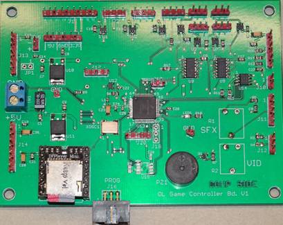
Eventually it was time to design the "OL Controller Bd." This would have the µC (microcomputer), logic and connectors to control the whole game. I used flip-flops triggered by the IR ball detector signals so multiple detections could occur simultaneously without being missed. It would provide the I2C commands to the Lighting Driver Bd, SPI (Serial Peripheral Interface) commands to the LED Matrix Bds (scoreboard), SCI (Serial Communications Interface) asynchronous commands to the Video Player & mp3 player. It would look for signals from the 3 buttons as well as drive their LEDs. It can gate off the signals to the flipper drivers to disable them between games as well as turn the ball delivery "wheel" on and off. Also on the board I designed in an mp3 player module controlled with another SCI port. While greatly reduced by using several serial protocols, it still had 20 some connectors.
Audio & Video
I thought I would make the project a combination old fashion pinball machine and newer arcade style game. On the old fashion side would be the flippers, the playfield inserts with points and most significantly, chime sounds when you score.
On the hi-tech side is the square pixel white LED dot matrix scoreboard, audio clips and the inclusion of a 10" monitor in the upper right of the playfield.
I used the mp3 player module located on the Controller Bd to play 4 different chime sounds when you score in the 4 different levels. It also plays a sinister voice from the show at the beginning and end of a session. When you get to a 5000 point threshold, you get Bonus Time of an additional 30 seconds, and hear a Zanti scream as all the game's lights go out except a bright strobe on the Zanti's face! The mp3 player module drives the left speaker. To drive the monitor, I used a great little video player, the MedeaWiz Sprite. It reads either a USB drive or SD card and plays video files. What made me use this player is that it also accepts TTL level serial commands. I used the other SCI port on my µC to send it commands at the right time to choreograph the videos.
Fortunately we have the series on DVD. I spent days going through them with a video editor, creating short video clips of key monster scenes, frame captures for the playfield graphics and sound clips. I wanted the monitor to play the great "Do Not Adjust You Set" control voice opening and then the closing theme when in "Attract Mode". During play, I have it playing a series of short clips from the show that I put together. The audio for the video plays through the amp I mentioned earlier and comes out the right speaker.
One more thing on the hi-tech side. Tinycircuits.com sells the "TinyTV", a high quality 3D printed 1950/60s TV set that plays mp4 files on it's little screen. It comes as a simple kit with an unpainted cabinet. On their site they have a 3D model which I downloaded to see if it would fit into my game. I only have a small space between the front glass and the playfield's clear lexan overlay. With the 3D model, I found that it would just fit! I showed it to Linda and she said I just have to add it. She did a beautiful job painting it in grayscale. I have it playing (with no sound) all my video clips that I made for the big 10" screen continuously. I put it in a living room scene in one ball guide protected area of the playfield.
My Outer Limit
After getting everything working, I had to take it completely apart for Linda to paint the cabinet. I finished the huge task of incorporating all the monster images I had culled from the show onto a star field background for the playfield graphics (using paint-dot-net) . I updated and used my drawing of all the ball channels as it's own layer so that the graphics would fit inside open areas and not be hidden. Then I had the whole thing printed as a gray scale gloss poster.
When all the pieces were painted, we glued the poster to the playfield, overlayed the now drilled lexan and I reassembled the entire game. I had pretty much finished the software in the original construction, but added some details.
The overall effect is an attack on your senses with the loud smack of the flippers, the ball hitting everything, the chimes, the lights, the Zanti, the TinyTV, the show clips video & audio. That's the chaotic pinball environment I wanted.
The game was finished just in time. I was reaching my personal outer limit after 6 months of work. We took it up to our "Diner" where we had to move things around to make room. We started playing it and sure enough, once again Linda beat me at my own game! |
|
(Electronics/PCB Design, Software, CNC, Woodworking, 3DP, Solenoids, AC Motor, Sound Editing, Video Editing, Artwork) |


|
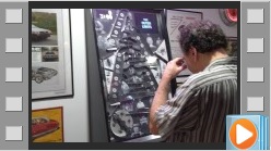
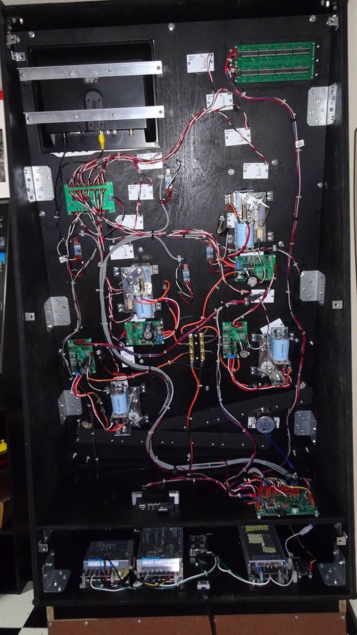
Above: Internal photo showing all the wiring. It’s hard to see as it’s so black, but there’s a bottom compartment that has all the power supplies & front panel components. The shelf above that has the Video Player and Control Board mounted on top of it. The white rectangles are the backlight boards for the 16 playfield inserts. Some of them are under flippers or flipper driver boards and can’t be seen.
To the lower right on the playfield board is the round AC motor that drives the ball delivery wheel. The flipper assemblies have the light blue coils. At the top are the 10” monitor and scoreboard. Below the monitor is the Lighting Driver Bd that controls all the LEDs in the playfield inserts, risers and Zanti face illumination. The very small blue boards are the IR ball detector circuits. |
|
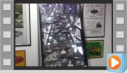
Above: just completed making the ball guides, though there will be several modifications and additions. |
|
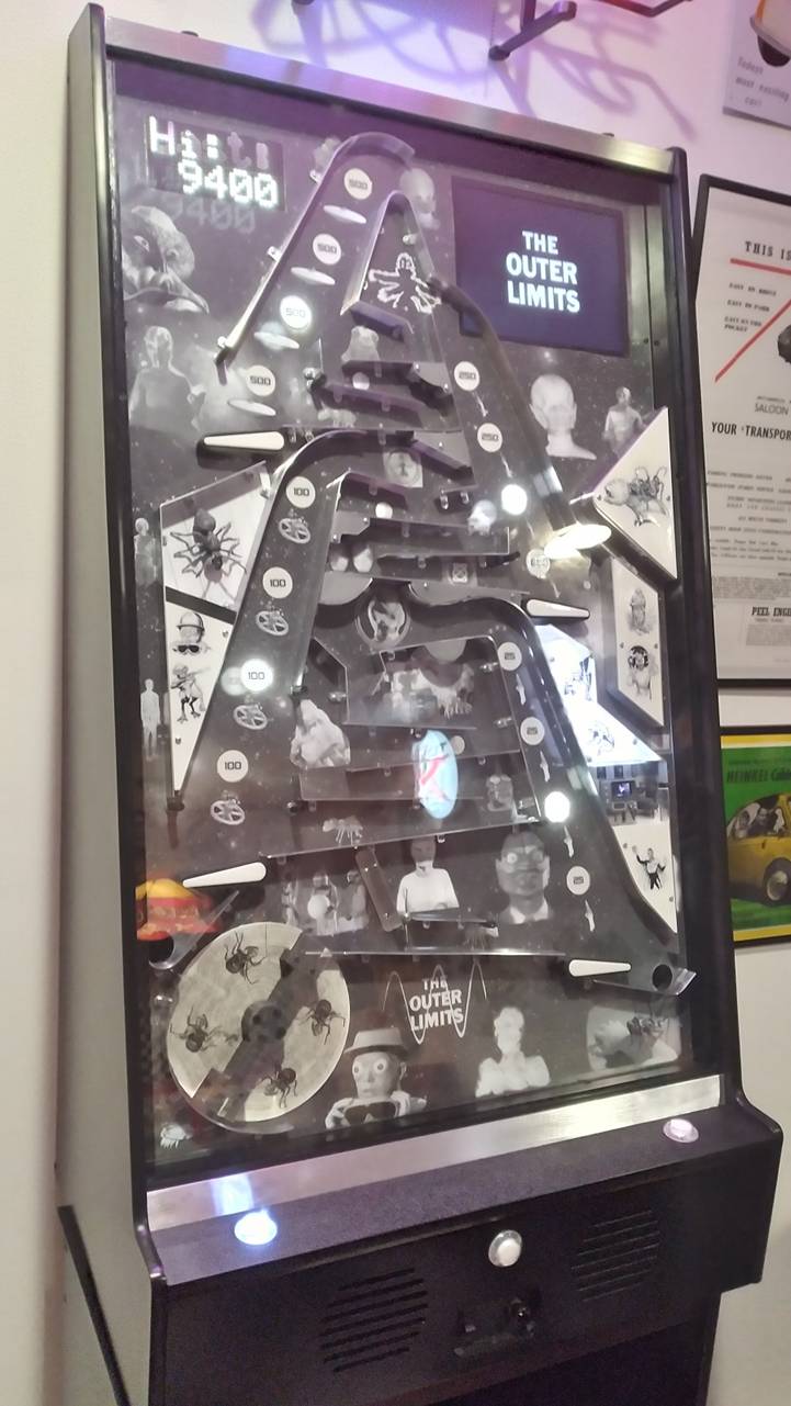
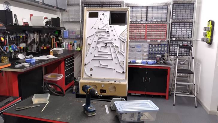
Above: The first time assembling the whole game. It can't be played here because I just drilled the playfield insert holes. Next it had to be disassembled, the lexan put in place and hundreds of holes drilled into it. |
|
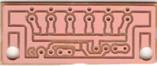
Left: Controller Board Above: Flipper Driver Board |
|
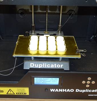
Left: 3D printing the playfield inserts on glass
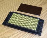
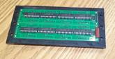
Right top & center: LED Matrix scoreboard in it's 3D printed frame
Right bottom: small CNC'd PCB for LEDs to light up Zanti's face |
|
Here I'm using my sheet metal punch to get rid of the entire 1/2" side of this 1/2" x 3/4" .062" aluminum extrusion angle except for the little "feet". You can see one of the feet hanging out to the right. These feet get shortened and rounded off a little, then drilled with 1/8" holes for #4 sheet metal screws. The screw go through the clear lexan, through the playfield graphics poster and into the playfield board. |
|
Below: Zanti waiting to bite my fingers off! |
|
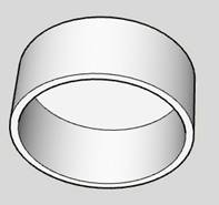
Below are various CAD models that were 3D printed or CNC’s. It’s just a small example as there were many more parts made. |
|
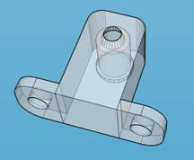
Left: one of the risers which gets a “monster” line drawing. Below: xray view of typical IR emitter/detector housing |
|
This is the little platform that creates the “living room” set where the TinyTV plays “Outer Limit” clips. |
|
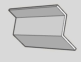
Ball “subway” angle behind playfield. |
|
Playfield insert, gets backlit and has point value decal. |
|
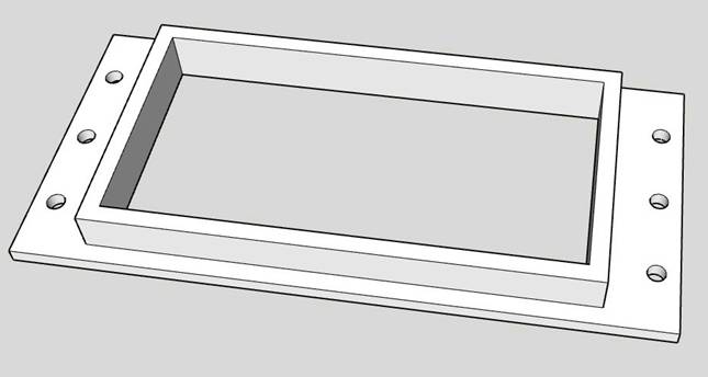
Below is the frame for the 2-line, square white-pixel scoreboard assembly. |
|
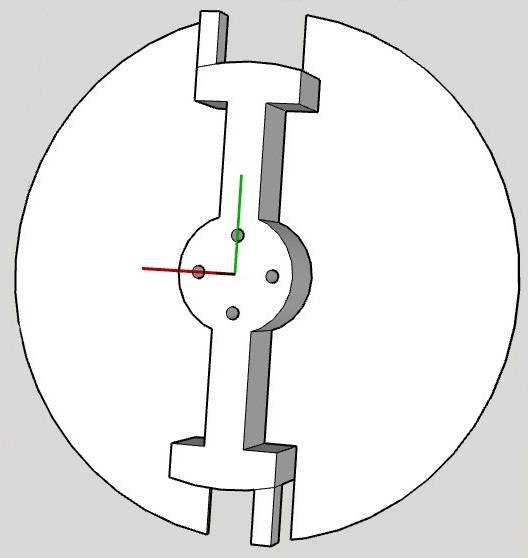
Below is the “wheel” & “rotator” assembly. The wheel is CNCd out of Garolite, the rotator is 3D printed in dark gray. It picks up the ball at the bottom and delivers it to the first ball guide at the top. |
|
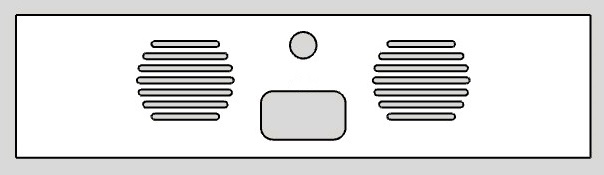
Below is the CNC’d front panel. It holds the start button, panel with the power switch & volume control and the two speakers. |