|
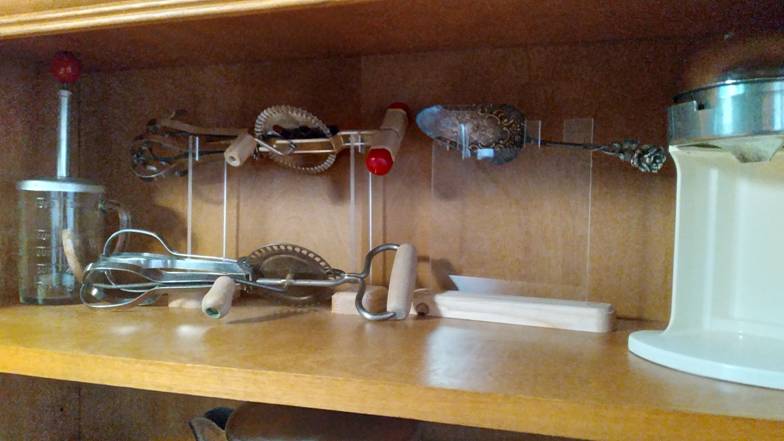
[2023-11-04] Linda has a great display area for antique kitchen utensils. To leave more space, she wanted me to make stands to raise a couple things above the shelf surface. I CNC’d wood bases with some contour and slots for the vertical acrylic that holds the mixer and pie utensil. CNCing acrylic is a little difficult, but I like the results and have some thoughts for future projects.
|
|
Electronics & Maker Projects (page 22) |
|
(CNC) |
|
Acrylic Display Stands |
|
Solar System |
|
(Electronics/PCB Design, Software, CNC |
|
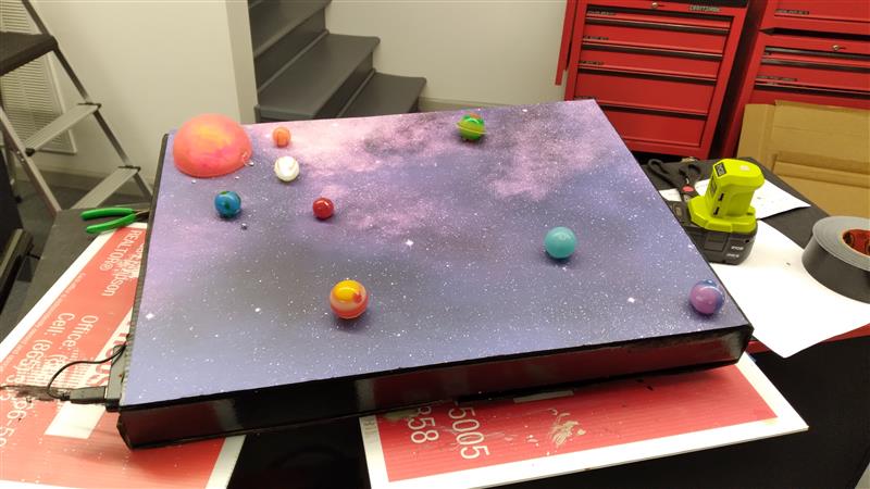
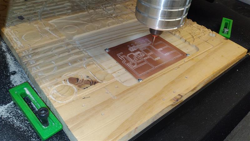
[2023-12-10] Our friend’s little boy had a school assignment to make a model of the solar system. They were allowed help, so I decided to add a little interest by making the sun glow and the planets light up sequentially. While I could have done this with a simple counter/decoder, I decided to use a cheap chinese knock-off of one of my 9S08 20pin SOIC µCs. I designed a board and CNC’d it. It holds all the electronics and the LEDs for the always-on Sun, as well as connectors that go out to the plant’s LEDs. I used a USB cord for power so that he could power it from a USB battery pack during his presentation.
|

|
SOIC 20-pin µC Tester |
|
(Electronics/PCB Design, CNC) |
|
[2023-12-20] When doing the Solar System project above, I used one of my recently acquired 9S08 20-pin surface mount SOIC packaged µCs (micro-computers). These are chinese knock-offs of a small version of the Motorola/Freescale/NXP family of µCs that I use for everything. I bought them because they were cheap. But being surface mount, once you solder them to the board, it’s a huge hassle to take them off if they are defective. And I certainly don’t trust chinese parts.
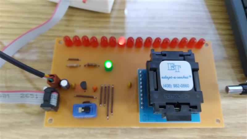
I decided to make a test fixture to verify operation before using them in another project. Fortunately I had in stock, left over from my career, an SOIC ZIF socket. This is a special, expensive socket where you lift the top, drop in your IC and close the lid. Contacts mate up with your IC leads allowing you to test the chip without soldering it to a board. I went ahead and designed and CNC’d a simple little board similar to the solar system project that incorporated this socket, 16 LEDs, programmer connector and power supply connector.
With this, I can program the DUT (Device Under Test) to just sequentially drive the LEDs using all of it’s 16 available I/O ports. This is really all the test it needs to be pretty sure the device is functioning.
|
|
Nibbler’s Aluminum Tiki Bar |
|
(CNC) |
|
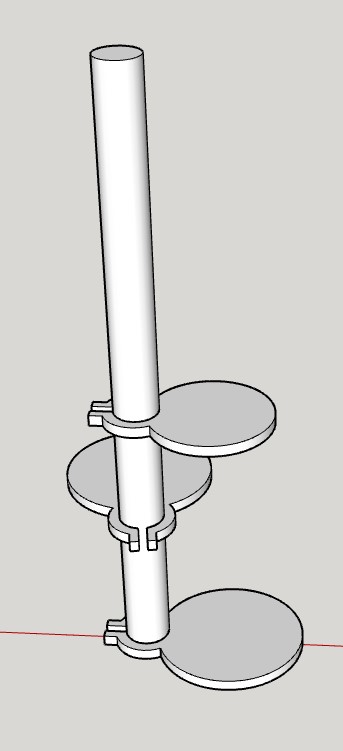
[2023-12-30] We had to be sure nothing in Nibbler’s house could harbor fungus, so everything needed to be made of metal or regularly washed fabric. One of the things she loved in her house was this hanging wooden platform we dubbed her “Tiki Bar”. We always pictured her sitting there with a Mai Tai.
I happen to have a large solid aluminum rod in stock. I designed around it to match her wood Tiki Bar, including the diameter of the levels. I gave 2D models of the levels to my friend John who’s a metal master. He CNC’d the round aluminum plates. I drilled & tapped them for set screws and put it together. She didn’t seem to notice the difference!
|


|
WrenchClock |
|
(Electronics/PCB Design, Software, CNC, Woodworking, Servo Motors) |
|
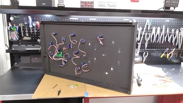
[2024-03-15] We have one purchased clock in our guest bedroom. The rest of the house, lab & shop are filled with ones I made in one form or another! The only area that doesn’t have one is in the CNC shop. I was going to make another LED matrix clock, but then I thought it should have a tool theme. What if I made a 7 segment display, but instead of 7 segment LEDs I used actual wrenches? Seems simple.
I went through my combination wrenches and thought the 1/4” would be a good size. In my Craftsman set, the 1/4” wrench was about 3.9” long. Seemed just about right, so I began to do a quick drawing. Well, I didn’t want to spend over $5 a piece for the 23 wrenches (plus a few spares) that I would need. Looking around I found a great deal on 1/4” “Klutch” wrenches at Northern Tool. It was some kind of clearance sale but when I went to the store they didn’t actually have any to look at. Nowhere online did it give it’s dimensions. So, I went ahead and ordered about 27 of them and it came to less than $1 a piece. After a long wait, when they did arrive, they were 4.66” long! Back to CAD where I began putting together the real, somewhat larger design.
The basic concept would be that the front window of the enclosure is acrylic to which I applied a polarized film. Each wrench is like a segment of a 7-segment display and has a rectangle of polarized film attached to it's front face.
The ones that are visible-when-vertical get film that is cut with polarization running parallel to the length of the wrench, and the ones that are visible-when-horizontal get film that is cut with polarization rotated 90° from running parallel to the wrench. That way, when I rotate a wrench 90°, it disappears against the black background. Actually, I've ordered some non-glare polarized film to play with, as the shiny stuff I used shows some reflection against the flat black background. It's good enough though given the art/experimental nature of the project.
I realized early on that some of the wrenches would have to pivot into that digit’s space and there would be interference. In CAD I created rectangular boxes and put scanned images of the wrenches inside. From there I experimented with various pivot points along the length of the wrenches. In the end, most of the wrenches would pivot at about 1/4 of their length from the end. Only the center wrench would pivot in the middle.
I drilled each wrench so I could use tiny screws to attach each one to a servo. This was really difficult as regular drill bits wouldn’t even scratch the wrench’s surface. I ended up using carbide endmills and drills. Even with those, I ate through probably 12 of them drilling the 46 wrench holes (two each). There went part of my savings on the cheap wrenches. Then I had to countersink them all. Painful.
It's all controlled by a µC, for which I ended up designing a custom board along with a multiplexer board for each digit and a button/LED board for status and control which mounts on the side. When I was breadboarding my first experiments, I realized that I would have to use the more expensive servos with feedback so I could actuate them in the proper order by having a “From >> To” numeral goal. There went the rest of my cheap wrench savings. That required reading the feedback voltage of each segment/servo and deciding what numeral that represented to establish the “From”.
As I needed the wrenches/segments to fold into their own digit space so as not to hit the adjacent digit's segments, I had to compose a huge 1000 step table that would define the choreography to go from the currently displayed numeral to the next. In the end I had to calibrate each segment's PWM (Pulse Width Modulation) signal and also it's feedback voltage. To allow all this manipulation, I set up a structure where I could send commands through a serial interface to position each segment in various ways and read all the feedback voltages from a terminal.
For the colon I used two large jam nuts (to keep them thin). Each has a servo and polarized film. During the approx. 11sec. it takes to update from one minute's time to the next, I have them rotate back and forth each second to give a "flashing colon" effect like an old LED clock might have.
Every day the clock goes out on WiFi to fetch the exact time and update it’s RTC (Real Time Clock), which has a battery backup. In the end, I have the clock default to "Standby", indicated by one of the LEDs on the side, because the servos make so much noise and would wear out if left running. I just hit a button on the side to take it out of standby, then it waits for the next even minute and updates it's display, then of course again every minute until it times out after 15 min. or the Standby button is pressed again.
|


|
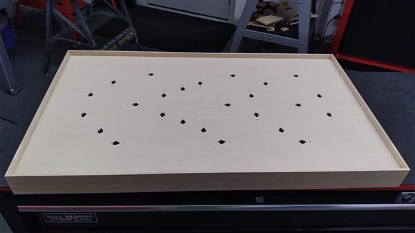
Main panel CNC’d for the odd shaped servo’s necks to poke through. |
|
In the process of mounting the 23 servo motors. |
|
Here starting to attach the servo “horns” with the drilled wrenches on top. |
|
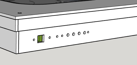
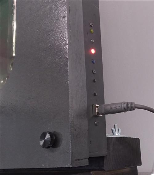
Side control panel. The top LED glows yellow when WiFi is active. Next LED down flashes green all the time when clock is in sync, red when not. The bottom red LED, here on, signifies Standby condition.
Under those, the top push-button forces a WiFi time fetch. The bottom pushbutton toggles Standby. Powerup default is Standby.
Under that is a USB connector used just for power. |
|
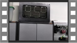
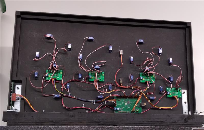
The rear panel shows all the wiring, which looks much like a small version of my vertical pinball machines! At the lower left is the control panel board. The little blue boxes are the 23 servo motors. The 4 smaller PCBs are the multiplexer boards. They mux Out the PWM signal to the selected servo motor and mux In the feedback voltage of the selected servo motor. They also switch power to their digit’s servos. The digit “hours tens” doesn’t need feedback since it only displays “1” or “blank” and has no interference problems. The colon is directly controlled by the processor board which is lower right of center as seen above. |
|
Copier Paper Tray Cover |
|
(CNC, Acrylic Work) |
|
[2024-03-22] At the end of 2022 I bought an extravagant Xerox color laser printer that does 11” x 17”. I can never keep an ink jet printer working as I use it too infrequently. After all the big projects I’ve been doing, I’m tired of taping 2 pages together for my schematics, which are usually 11x17. This was by far the cheapest machine you could get, and I bought it with just one paper tray which I use for 11x17 paper.
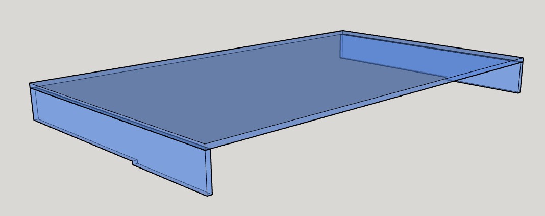
However, since it can do color I occasionally use it for 8.5”x11” (letter) size printing. Fortunately, a side direct feed folds down where you can put whatever paper you want. So, I keep normal letter size there. Being out in the open, though, has it getting dusty over time. I decided to take some measurements and create an acrylic Paper Tray Cover to put over the side feed and always leave it down.
It’s always rewarding CNCing acrylic, and this time I learned how to do real acrylic bonding with the proper solvent. |

|
LCD Handheld Terminal |
|
(Electronics/PCB Design, Software, CNC, 3DP) |
|
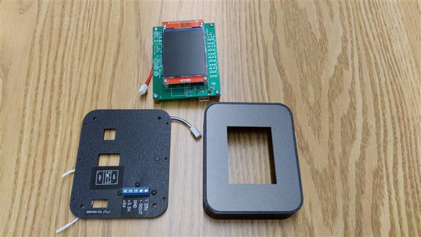
[2024-04-03] When working on the WrenchClock project, I used both a small dumb terminal and PCs running a terminal program to communicate serially with the clock. In software I had the clock respond to a whole set of simple commands that let me calibrate the wrench positions and read back the servo’s feedback voltage values. Most of my larger projects get developed using this approach. Since I had done so much work with the color LCDs I used in The Invaders pinball game, I decided to use one to make a small terminal.
I use the LCD in portrait mode to display text as it is received serially. The main connection to a project is provided by a rear panel terminal block (blue in the photos). I used this because it’s the simplest way to quickly hook up something with just wires, no connector needed. I designed and CNC’s a small PCB that hold the terminal block and allow me to mount it on the rear panel.
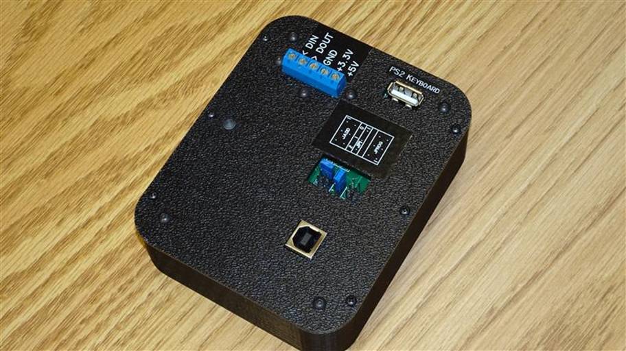
Sometimes a project will just spit out information that I can watch on a terminal. Usually though, I need to also send it commands. Therefore, I included a USB Type A receptacle on the rear panel for a PS2 type keyboard to plug in. Decoding an actual USB keyboard requires a host processor and is very involved, having done it once before. However, I have a whole box full of very small keyboards that have dual USB/PS2 functionality. PS2 keyboard data is much simpler to decode, and I use a tiny 16pin µC on the LCD controller board to receive keyboard data, convert it to ASCII and send it to the main µC via I2C bus. This way I can send and receive characters to my target project.
On the rear panel I used a USB Type B connector to power the terminal. As long as I was putting that on, I also included a USB to serial IC to that I can send and receive characters from a PC via USB in addition to the rear panel logic level terminal block connection.
Since it’s a color screen, I show the incoming text as green and highlight the next line with a light purple. This line also serves as a text divider when the screen rolls around to the top again. I put a small yellow box at the bottom of the screen to type in a text string to send.
I wanted it to look like a nice piece of test equipment. I 3D printed the housing with a little ledge on the inside perimeter. Then for the front panel I CNC’d some bronze plastic sheet that settled down into that ledge. It has a cutout that lets just the active part of the screen show.
For the back panel, I CNC’d a thin textured ABS plastic with all the cutouts for the two USB connectors, the terminal block, and an opening for the µC programmer connector and some jumper selections.
It seems to be working nicely and I look forward to using it on future development projects. |


|
3D printing enclosure outside surround. |
|
CNCing small PCB for rear panel terminal block. |

|
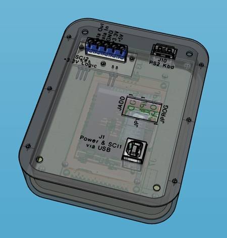
Some CAD views |