|
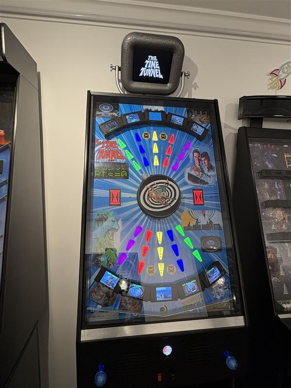
[2025-11-01] This project started with selecting the Time Tunnel as the theme, then working from there. I wanted the ball to represent Doug & Tony visiting random events in time just like the show. Since the Time Tunnel is roundish, I thought it should be in the middle and launch to time destinations from there. That decision ended up making the implementation quite the challenge.
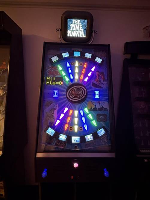
I made the centerpiece kind of a “turret” that rotates when the player pushes the left joystick Left & Right for CCW & CW. The turret has graphics showing Doug & Tony floating through time and a ball launcher tube that protrudes enough to aim with. When you think you’re lined up, tapping the right joystick up or down launches the ball.
Across the top and bottom are arrayed a total of 10 “targets”. The targets are actually 2.8” LCD screens held above the playfield by left & right “risers”. Shooting the ball under the LCD between the risers is how you score. Ball detection is done using an IR emitter & phototransistor. In this case, I’m using reflective mode where both the emitter and receiver are on the same side.
There are standard pinball “playfield inserts” with a kind of arrow shape lined up in columns of 3 that go from the turret aiming at one of the Targets. These inserts are the milky white type, and I have the year of the event that they point to decaled on their surface. The plastic is an excellent diffuser, so each insert has a small PCB behind it with 5 WS2812B smart LEDs. My controller board sends a pulse stream which tells each of the series connected boards what color to show.
On the left side of the playfield there is an LED matrix scoreboard. On the top line is the time remaining, counting down from 3:00 minutes. On the bottom line is the score in Points, which are from 0-10 where 10 is actually displayed as a “Win!”.
Back on my Outer Limits game, I had a monitor embedded in the playfield which showed clips from the show. I haven’t done that since and thought it would be a good addition for the Time Tunnel game. However, there’s no room for that in the playfield. Looking at my Alien Sidestep game, I have the scoreboard in a Marquee that’s on top of the machine.
Combining these two concepts, I decided to put a monitor there. A modern monitor just sitting there would look ridiculous, so I designed what I call a “SciFi” enclosure that kind of looks like it might come from the Time Tunnel control room. It’s suspended above the game by two curved metal arms and has some bold, old looking knurled knobs holding it in place and allowing angle adjustment.
Problem #1 Having a ball launch from a rotating turret was a lot more difficult than it sounds. The rotating platform is way too small to have a launcher solenoid mounted on it. My chosen specialty of vertical games gives me precious little space between the playfield and the glass. Even if I could, I’d have to have a hi-current slip ring arrangement to energize the launcher solenoid.
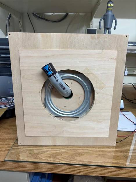
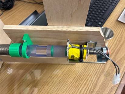
The only choice I could think of was to mount the launcher solenoid perpendicular to the rear of the playfield, kind of hanging out in space. Then I ended up using a few inches of a flexible spring to couple the ball path to a 90degree PVC conduit which would deliver the ball to the playfield. This coupling was due to the fact that there’s no way to perfectly align the rotating PVC pipe to the fixed exit tube of the launcher mechanism. There had to be some give as it rotates. I tried plastic and rubber tubing, but in the end I shoot it through the small length of spring.
I mounted the round internal rotating turret board to a 6” lazy-susan mechanism, with the other side of the mechanism mounted to the back of the playfield. I 3D printed a 6” roller-chain sprocket with a huge 4.25” hole/opening in the center. This opening allows for a 3DP support bracket holding the 90degree PVC conduit elbow which goes thru the center. Even with the modeling, CNCing and 3D printing, in the end I had to hand contour the rotating wood opening so it would facilitate the PVC elbow’s contour as it went through.
Problem #2 The next problem I have already faced before. In a normal pinball machine, the ball always ends up in the “drain” at the bottom of the playfield and gets re-launched from there. In my Invaders game I had to get balls from the bottom to the very top where they get dropped onto the playfield through a hole. For that game I ended up making an extremely elaborate mechanism utilizing 3 motors, multiple µswitches all with a dedicated µC to control it all.
This was so complicated that it steered the execution of my following game Alien Sidestep. There I avoided the whole issue by having the balls just fall back down to the launching area ready to be used, no transport mechanism needed.
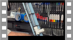
For the Time Tunnel game, I experimented with a completely different approach. I used a plastic roller chain, drilled out the pivot part of a link, then put a small #2 screw thru there with a tiny washer. I then 3DP little .75” “pegs” that I tapped for the screws and mounted them on the chain, perpendicular to the chain’s “side”. The pegs would go up a clear PVC tube, elevating a ball. See the CAD drawing and video of me bench testing the concept.
The ball elevator takes the balls to the launch tube fixed against the launch solenoid. I have another IR pair which look thru the tube to see if a ball is present. If not, software turns on the elevator motor and leaves it on until the next ball falls into the launcher, keeping up a fairly quick delivery of the balls for the player.
Attract Mode During Attract Mode, all the LCDs show their image representing an event in time, for example Tony on the deck of the Titanic. The playfield inserts put on a colorful fanning display. The scoreboard alternates between showing the current Hi score and the Last score.
The SciFi monitor plays the opening credits, music and announcer. When that is over, the monitor shows a silent continuous looping of the title and hourglass graphics. I have all my game’s Attract Modes go silent after the introductions to keep the game room useable without continuous sounds/music.
Game Play Mode When the player presses the Start button on the front of the game, an audio excerpt of the General in the Time Tunnel saying “Activate The Tunnel” is played. All the targets show the Time Tunnel logo. All the playfield inserts go to blue. The large backlit hourglasses on either side of the launch turret are green when a ball is available to launch or red when no ball is there and you can’t launch.
Then the first random target suddenly shows an image of it’s event in time. The column of 3 playfield inserts pointing to that target turn green. Now the player uses the left joystick to rotate the turret towards the active target and as soon as it looks lined up, taps the right joystick to Launch. You are only given a very short time that any one target is active, so you have to kind of launch as soon as you are lined up, maybe even as you are rotating!
If you get the ball through the target while it is still active, the LCD flashes reverse image on and off for a short time while a dramatic musical “stab” is played. That target now shows a kind of color-splash taken from the show’s opening which tags it as having been achieved.
If you miss, that target will go inactive, back to the logo screen, then after a short delay another random target will go active along with it’s inserts going green.
If time runs out before you hit all 10 targets, a losing video/audio is played. Likewise, if you get all 10 targets before time runs out, a winning video/audio is played. Either way, it then goes back to a fresh Attract Mode.
|
|
Electronics & Maker Projects (page 24) |
|
(Electronics/PCB Design, Software, CNC, Woodworking, 3DP, DC Motor, Solenoid Launcher, Roller Chains & Sprockets, Video & Sound Editing, Graphic Design) |
|
Launcher Mechanism |
|
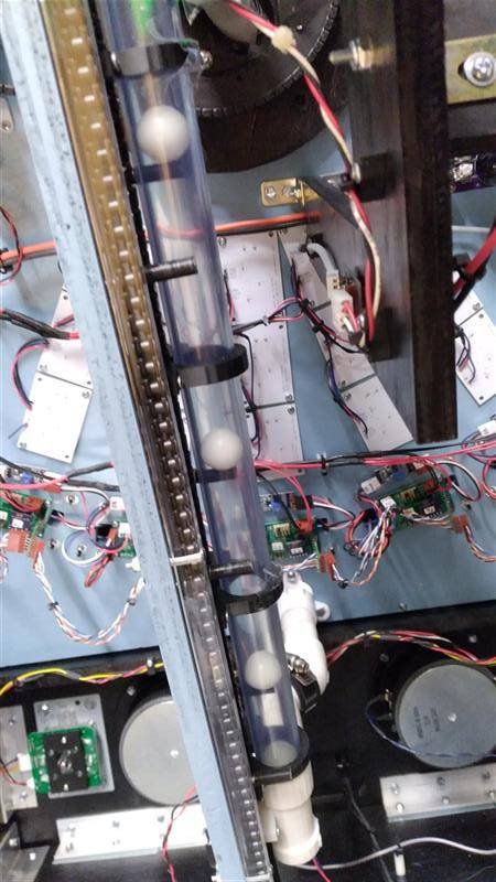
Inside of finished game. |
|
Time Tunnel Pinball Machine |
|
Detail of Ball Elevator |
|
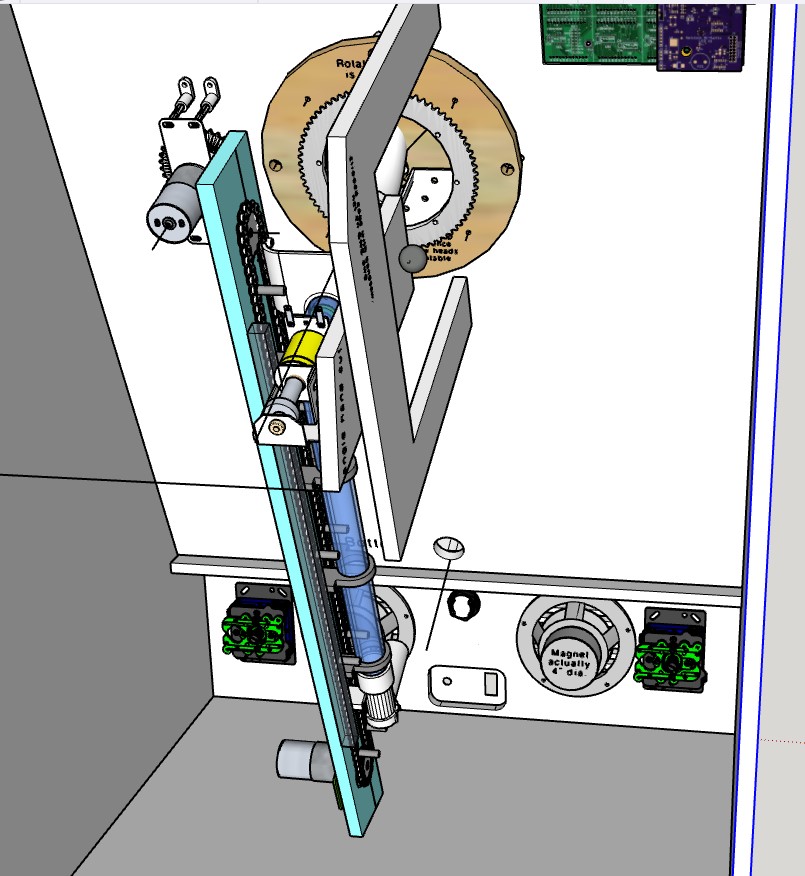
CAD view showing the two most complex mechanisms in this project. One, the rotating turret’s internal wood rotating member with it’s huge roller chain sprocket. To the left is the motor with it’s sprocket (chain not shown). Perpendicular to that is the launcher solenoid held in space by the large wood bracket structure. Two is the Ball Elevator with it’s clear blue-tinted PVC tube.
You can see it’s motor at the bottom moving the plastic roller chain, with the idler sprocket at the top. Pegs that I’ve attached at intervals to the roller chain elevate the balls up the tube. The complex 3D printed element at the bottom (white) accepts returning balls one at a time. It has at the bottom an angled entry point for the pegs that aligns them entering the tube, where a waiting ball in then introduced. |
|
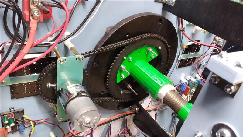
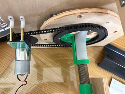
Roller chain and sprockets set up to rotate the turret. |
|
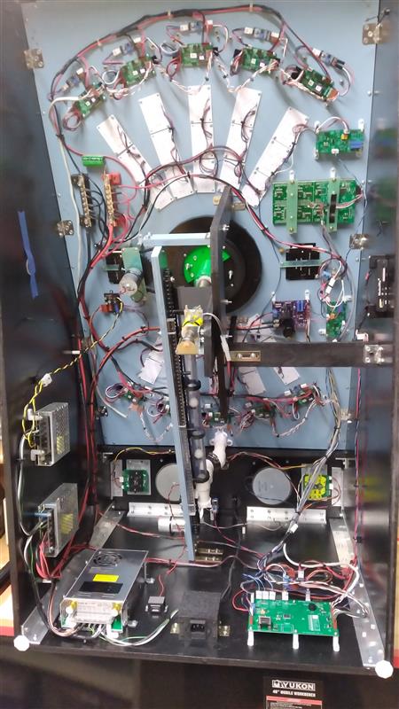
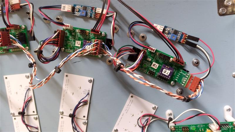
Tiny boards at top are purchased/modified IR detectors. The boards below that are LCD controllers, one for each target. They get commands via an RS422 bus from the Game Controller µC. The little purple daughter boards have a Flash memory chip. I can remove the boards and plug them into my downloader / programmer to write images that I download from a PC via USB. The white boards are for the WS2812B smart LEDs which rear illuminate the playfield inserts. |
|
Early experiments. |
|
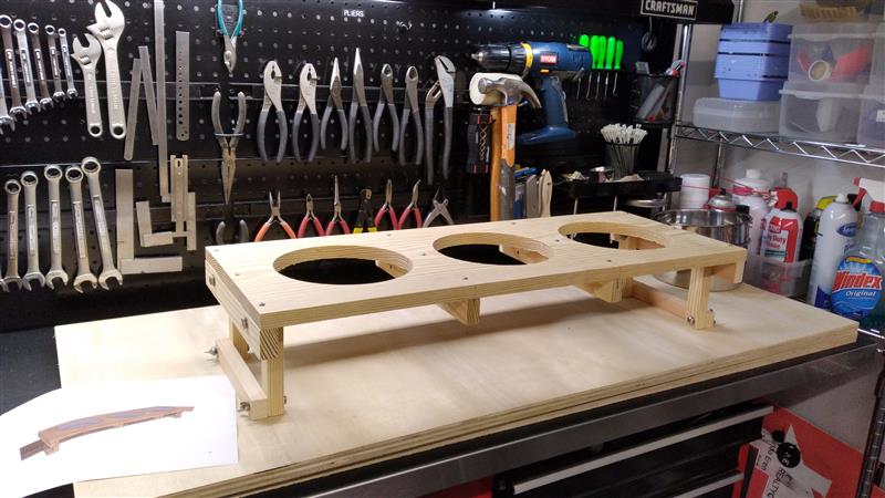
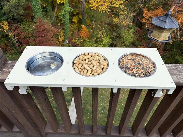
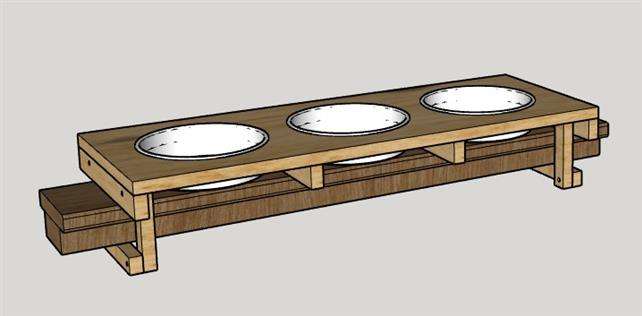
Bird Feeder |
|
(CNC, Woodworking) |
|
[2025-11-11] Linda wanted a new bird & squirrel feeder that would attach to our deck’s handrail. She already had the stainless pans, so I designed around those and the handrail. I used stainless hardware and Linda did multiple coats of paint to have it stand up to the outdoors as much as possible. |
|
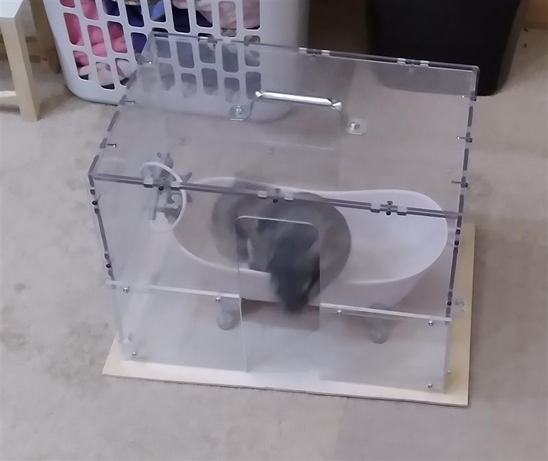
Nibbler’s Dust Bath |
|
(CNC) |
|
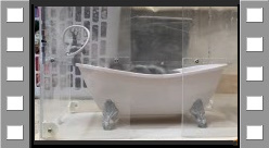
[2025-11-27] Our chinchilla Nibbler loves her dust baths. It turns out you can’t get a chinchilla wet, just like their relatives the Mogwai. So they take dust baths. Really. Linda made her first dust bath from Tupperware-like containers, and Nibbler really enjoyed that. When Linda saw a perfect size Clawfoot Tub she got it for Nibbler. The trouble is that the dust goes everywhere.
Now my first 3D printer, the Wanhao, had a rather elaborate plexiglass cover. I decided to add plexi to the bottom to get the height necessary for Nibbler to go thru the opening and hop in the bathtub. I CNC’d the plexi and used screws to put it all together.
Nibbler seems to love her new stylish tub with glass enclosure. Watch the video below. |
|
Nibbler’s Outlet Cover |
|
(3DP) |
|
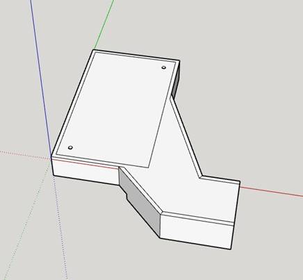
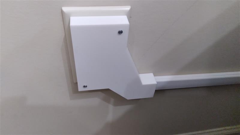
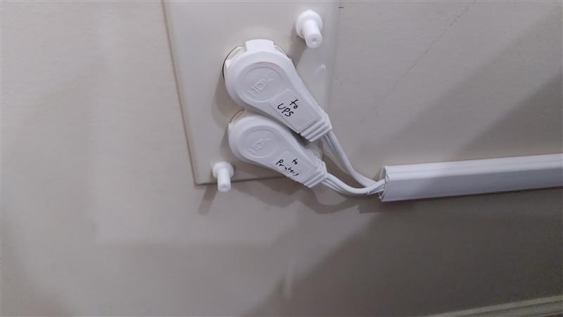
[2025-12-10] Nibbler bites everything! We let her out of her house to run around Linda’s office twice a day and there have been countless projects to protect her or the office. One situation is where 2 extension cords plug in where she can get at them. We’ve been putting something over them every time we let her out. For this project, I first put the cords themselves into surface channel. Then I designed & 3D printed a cover for the whole area. I also printed two standoffs where one end glues to the outlet face plate and I threaded the other end for screws. She nibbles at it but at now she can’t get shocked. |
|
Silver Clock |
|
(3DP, Electronics, Software, CNC, Woodworking) |
|
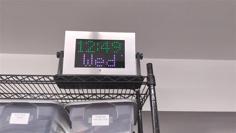
[2025-12-10] Yes, I know I make a lot of clocks. This one makes 8 (not including Wrist Clock). When I was developing Wrench Clock, I new I was putting it in the CNC Shop. What I didn’t realize was that leaving it on all time was no good. Too noisy and it wouldn’t last a week with all the mechanical aspects. So, as I mentioned in it’s write-up, it really is just an art piece.
But I still wanted a clock in there. Well, I’ve has this brushed aluminum frame I picked up cheap at a Walmart many years ago on one of the end displays of random clearance stuff. I think it was an optional frame for one of those stand alone slide shows. I thought finally I found a use for it.
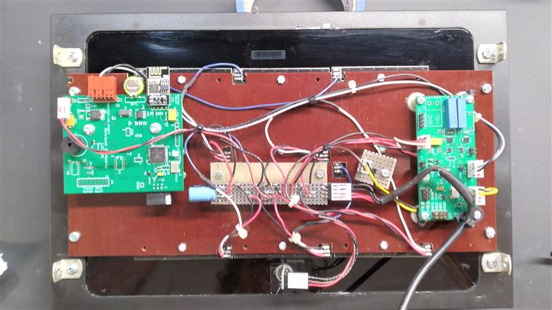
I used these 8x8 WS2812B matrix LED boards which I bought from Aliexpress as they were so cheap. I put two rows of 3 panels together and CNC’d a phenolic panel to mount them on with screw holes and openings for wires to exit. Rather than layout a project specific PCB, I used one of my WS2128B Controller boards along with one of my Netclock Bi-LED Matrix boards. Between the two I have everything I needed to make a clock that sets itself over the web. I also used a very small PIR (Passive Infrared) motion detector. That way the display will go out when no one is in the room.
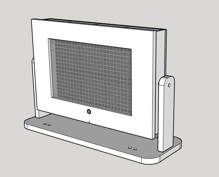
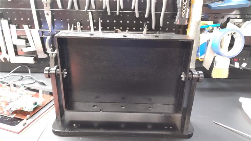
I used 1/4” plywood for the cabinet and 1/2” plywood for the base & support arms. Inside the chassis at the pivot holes in the left & right panels I put weld nuts that I had drilled for #2 sheet metal screws that held them in place. That allowed me to use 6mm knurled knobs on each side so the clock could pivot to any angle.
The wiring looks a little messy, but that stems from using multiple existing boards instead of a dedicated one.
|
|
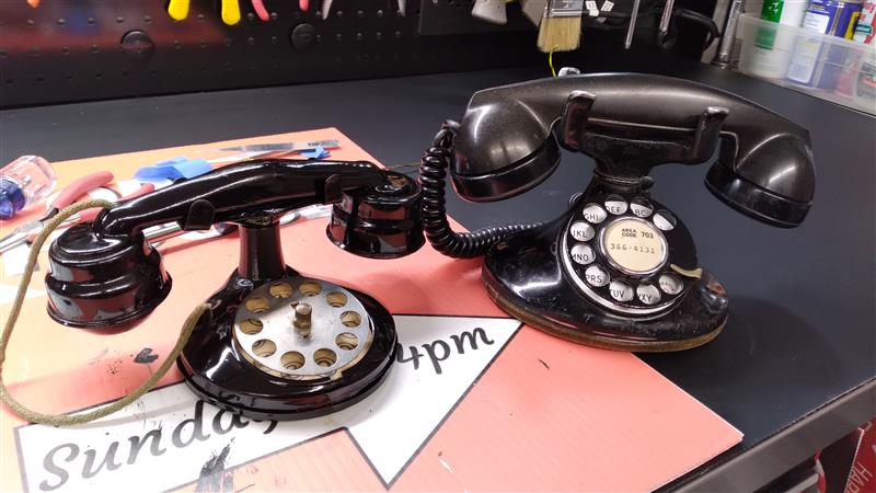
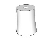
Toy Phone Cradle Support |
|
(3DP) |
|
[2025-12-11] Linda bought this antique tin toy phone which looks a lot like one of her real phones. It was quite worn and a red color. She was going to repaint it black but the toy’s cradle support was very tall and did not match the proportions of the real phone’s cradle. So I designed and 3D printed a cradle support with the same contours as the original but much shorter. |